
Machine Vision & AOI: Why Factory Inspection Fails Outside the Lab
Model accuracy matters, but stable imaging, representative data, cycle time, PLC integration and sustained compute are what turn an AI demo into production equipment.
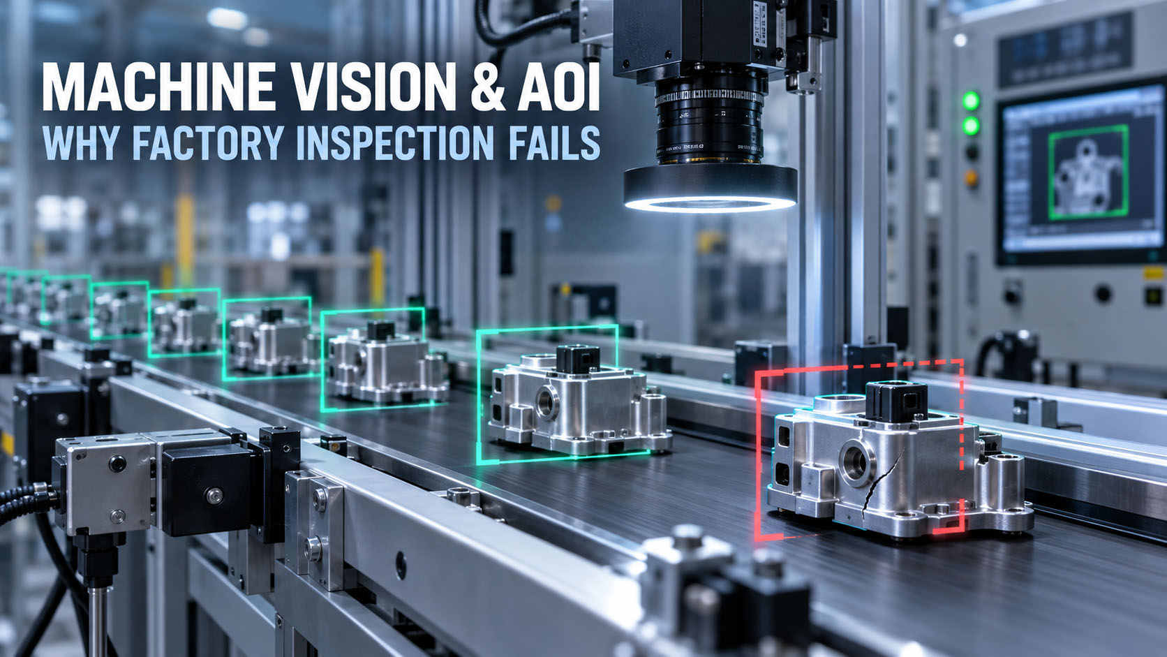
The lighting fixture, the camera mount and the PLC link decide as much of the result as the model does.
Table of Contents
1. The model is usually not the first thing that breaks
A useful pattern shows up whenever teams describe real factory vision projects in engineering communities. On one widely-read account of a PCB defect-detection build, the team assumed the AI model would be the hard part. The problems that actually appeared first were lighting, dataset generalization, inference speed, and thermal throttling — in that order.
The board had reflective surfaces and changing component heights, which produced glare and shadows. After improving diffuse lighting and normalizing the preprocessing, performance improved without changing the model at all. Treat that as a community engineering signal, not a benchmark — but the lesson generalizes.
If the raw image is unstable, a better neural network may only learn an unstable problem more accurately.
2. Lighting and optics are decided before GPU selection
Most machine-vision projects open with the wrong question — RTX 4060 or 4070, Jetson Orin NX or AGX, how many TOPS. The image pipeline starts earlier than the GPU.
The real chain starts at the part, not the processor
object → lighting → lens → sensor → image → AI
Everything upstream of the sensor determines what the model actually sees. A GPU decision made before the imaging chain is a decision made blind.
Reflective surfaces are the hardest imaging problem on the line
PCBs, machined metal, glass, polished plastic and automotive parts all fight the camera. They produce glare, hotspots, shadows, reflections and inconsistent contrast — the exact conditions that make a defect appear and disappear between frames.
Lighting belongs in the mechanical design, not in the accessory list
Diffuse, ring, backlight, coaxial, polarized and enclosed lighting each solve a different imaging problem, and the right one is part of the fixture.
The compute platform only becomes useful after the imaging chain produces a repeatable input.
3. Lab accuracy is not factory-line accuracy
A model can score well on a held-out test set and still fail when the production environment moves. That gap is where most “the AI stopped working” reports come from.
Dataset shift makes a model good yesterday and wrong tomorrow
Production changes constantly: a new product revision, a different component supplier, color variation, higher component density, a shifted camera position, lighting drift, a different surface finish, a new defect type. In the PCB project, the team reported good results on the initial test set and noticeably worse results once a different board variant was introduced. Those are reported project observations, not industry benchmarks — but the principle is reliable.
A model trained on yesterday’s production conditions may not automatically generalize to tomorrow’s product revision.
Planning for retraining, drift monitoring and a data-collection loop is part of the system design, not a later fix.
4. False positives can destroy AOI return on investment
Vision marketing focuses on detection rate. Production teams also live with false alarms, and false alarms have a cost that compounds: too many false positives create a manual reinspection queue, the queue causes operator fatigue, fatigue slows the line, and a slow line erases the ROI the AOI was bought for.
A useful AOI system finds defects without creating an unmanageable review queue.
In production terms, that means balancing precision (how many flagged parts are truly defective) against recall (how many real defects are caught), and treating the reinspection workload as a first-class metric — not an afterthought behind a headline accuracy number.
5. The best AOI targets are narrow, measurable defects
There’s a consistent pattern in successful inspection deployments: they don’t ask AI to decide whether a product is generally good or bad. They define the task around specific, measurable defects — short circuit, open circuit, void, dent, protrusion, scratch, crack, corrosion, weld quality, missing component. Reported use cases across manufacturing-AI case collections include PCBA defect detection, glass lens module inspection and LCD panel inspection built exactly this way.
The narrower and more measurable the inspection target, the easier it is to validate the complete system.
A representative PCBA inspection flow
PCBA → controlled imaging → defect model → short / open / missing / surface defect → pass or review
The controlled imaging step is doing as much work as the model.
On third-party reported case metrics
One third-party manufacturing-AI case collection reports figures such as defect-recognition precision above 92%, issue-processing time under 0.3 s, and product-detection rate above 98.6%. These are third-party reported case results, attributed to that case provider — they are not BITECH test data, not industry-standard accuracy, and not a guarantee of performance in your application. Real numbers depend entirely on your parts, defects, imaging and validation.
6. Cycle time decides whether the vision system is usable
A model that can detect a defect is not automatically fast enough for the line. The PCB project reported a mismatch between full-resolution inference time and the production cycle-time target — a common outcome. The team recovered throughput with ROI cropping, separating image capture from inference, and preprocessing optimization, rather than a bigger GPU.
Size from the line, not from the datasheet
line speed → available inspection window → camera count → image resolution
           → model complexity → required compute
Required cycle time should define the compute requirement — not the other way around.
7. Camera count changes the computer requirement, not just its size
A one-camera system and an eight-camera system are different computing problems. Camera count, resolution, frame rate, trigger rate, image format, Ethernet and USB bandwidth, decode and preprocessing, and concurrent inference all move together.
| Vision system | Typical compute pressure |
|---|---|
| 1 camera / low FPS | Low |
| 2–4 cameras | Medium |
| 4–8 high-resolution cameras | High |
| Multi-camera + multiple AI models | Very high |
Global shutter, synchronization and transport are part of computer selection
Industrial cameras add system-level requirements that are easy to miss: global shutter to freeze motion without distortion, a minimum guaranteed frame rate, multi-camera synchronization, and a defined transport — GigE Vision, USB3 Vision, GMSL2, CoaXPress or Camera Link. The camera interface is part of the computer decision, because the host needs the ports, the bandwidth and the SDK support to match. For the multi-camera transport choice specifically, see GMSL2 vs GigE Vision for industrial multi-camera systems. paying for the second when you need the first is waste, not safety margin
8. The industrial PC must move the images before it can run AI on them
camera → interface → memory → preprocessing → GPU → result
Any stage can be the bottleneck — PCIe bandwidth, Ethernet bandwidth, the USB controller, the CPU, RAM, NVMe, the GPU itself, or the camera SDK.
The fastest GPU cannot compensate for an image pipeline that cannot feed it fast enough.
This is why a machine-vision industrial PC is sized as a whole system — I/O, CPU, memory bandwidth, storage and GPU together — not by GPU model alone.
9. PLC integration is part of machine vision, not an afterthought
A vision system is only useful when its result can drive the line. A recurring theme in automation discussions is a team that gets a Python vision model running on an industrial PC, then hits the real question: how does the result reach the PLC so it can control the conveyor and the sorting servos? Product-handling verification, assembly inspection and process verification all live or die on that link.
A workable vision-to-PLC architecture
camera → industrial PC → AI inference → pass / fail / coordinates → PLC → reject / stop / sort
The communication paths that carry that result are standard industrial ones: EtherNet/IP, PROFINET, Modbus TCP, OPC UA, plain TCP/IP or digital I/O. Which means the vision computer needs the right industrial interfaces, not just a GPU.
An edge AI computer plus a PLC beats asking one device to do everything
A common question is whether the AI computer should also replace the PLC. Usually it shouldn’t. The durable pattern keeps the industrial PC on compute-heavy vision, AI, database and UI, and the PLC on deterministic I/O, safety and motion.
Use the industrial PC for compute-heavy vision and keep deterministic machine control where it belongs.
This isn’t mandatory for every machine — some simple cells are fine on one device — but for anything with real-time motion or safety, the split is the safer architecture.
10. Smart Camera or PC-Based Vision Is an Architecture Decision
A self-contained smart camera can be the better production choice for standard inspection tools, straightforward PLC integration and a maintenance team that values a vendor-managed ecosystem.
PC-based vision becomes more attractive when the system requires multiple cameras, custom AI, multiple models, databases, MES integration or a broader software stack.
The choice is about architecture and lifecycle, not simply camera price versus PC price.
Deep dive: Smart Camera vs Industrial AI PC →
11. Don’t overspec the industrial PC before the workload is defined
Automation teams regularly flag the opposite failure too: enclosure-mounted vision PCs specified with Core i7-class hardware that the real workload never uses. The useful question isn’t what the biggest box is, but whether this task actually needs a Core i7 or a discrete GPU.
The answer depends on camera count, resolution, rule-based versus AI inspection, model size, cycle time, database and HMI load, and any concurrent workloads. Rule-based inspection on one camera is a very different machine from multi-model deep learning on eight — and paying for the second when you need the first is waste, not safety margin.
12.Short Benchmarks Do Not Prove Production Stability
The PCB project reported a system that performed well initially and then hit thermal throttling during sustained operation — the classic gap between a demo and a deployment. AOI runs continuously, and continuous vision load (cameras + decode + CPU + GPU) generates heat that a five-minute benchmark never reveals.
Eight questions to ask before approving a vision computer
- 1What is the ambient temperature at the installation point?
- 2What is the sustained CPU load, not the peak?
- 3What is the sustained GPU load?
- 4How many cameras are connected, at what resolution and trigger rate?
- 5How long was the test run?
- 6What CPU and GPU temperatures were reached?
- 7Were the clocks stable across the whole run?
- 8Did thermal throttling occur at any point?
Factory AOI needs sustained throughput, not a five-minute benchmark.
The evidence that matters is a sustained-load test with a stated duration and ambient temperature — the kind measured in a validation lab, not on a spec sheet.
13. Watchdog, storage and lifecycle decide whether the line keeps running
Once vision is part of production, a computer failure isn’t an inconvenience — it can stop the process. So an AOI industrial PC is judged on more than frames per second: a hardware watchdog to auto-recover a hung system, storage sized and rated for continuous image logging, wide-temperature and fanless or filtered cooling for the enclosure, stable drivers, and a lifecycle long enough to stay available for the life of the machine it inspects. A consumer box that’s fast today but gone from the catalog in eighteen months is the wrong foundation for a line that runs for a decade.
14. How to size an industrial computer for machine vision
Imaging
Camera count, resolution, frame and trigger rate, and transport — GigE Vision, USB3 Vision, GMSL2, CoaXPress or Camera Link.
Inference
Rule-based or AI, model size, number of concurrent models, and the target cycle time the line allows.
Integration
Which PLC protocol (EtherNet/IP, PROFINET, Modbus TCP, OPC UA, digital I/O), plus database/MES and HMI load.
System
CPU, RAM, NVMe for continuous image logging, GPU or NPU, and the I/O that bridges cameras and automation.
Deployment
Ambient temperature, 24/7 duty, enclosure type, hardware watchdog, and required lifecycle.
Those answers point to a platform class. Used as general-purpose industrial vision computers, BITECH platforms map roughly like this:
- Rule-based or light AI, one to a few cameras — an efficient x86 box PC or RK3588-class edge AI computer such as the AE-3588 family, fanless, with industrial I/O for the PLC link.
- Multi-camera vision and mid-size inference — a Jetson-class platform such as the AE-NJ60BT, with GMSL2/GigE camera ingress and CAN/LAN for automation.
- Heavy multi-stream deep learning or several models — an x86 + RTX MXM platform such as the AE-760EBT for GPU-class AOI, with sustained-load cooling.
- Frame grabbers, 10GigE NICs or add-in cards — an industrial box PC with the right PCIe slot and industrial I/O (see the PCIe Expansion Selection Guide).
Pick by the defined workload, not a fixed GPU — and confirm the sustained thermal behavior before you commit.
Bottom line: the best AOI system is the one that survives production
A machine-vision project does not become production-ready when the model hits a target accuracy. It becomes production-ready when the complete system can repeatedly acquire a stable image, process it within cycle time, communicate the result to the automation equipment, sustain that performance under factory conditions, recover predictably from faults, and stay supportable over the required lifecycle.
In AOI, model accuracy matters — but lighting, data quality, integration and sustained compute are what turn an AI demo into production equipment.
Design the imaging, the data, the cycle time, the PLC link and the thermal envelope together. The model is one part of the system, and the system is what ships. For a full deployment view, see the Machine Vision & AOI solution.
Get a platform recommendation
Get a Production Vision Readiness Review
Send us the inspection target, imaging setup, cycle-time target and production environment. We’ll identify where the deployment is most likely to fail before hardware is finalized.
Send us six things
- Inspection target
- Smallest defect
- Camera + lighting/ trigger rate
- Cycle time
- PLC / robot
- Ambient / duty
We come back with
- CPU / NPU / GPU architecture
- Camera / network topology
- Required industrial I/O
- Thermal / power assumptions
- The closest BITECH platform
- A sample configuration
OEM / ODM · Sample evaluation · 24-month warranty · Long-lifecycle platform options
Machine Vision & AOI
Frequently asked questions
-
Because production AOI is a complete imaging, compute and automation system, not just a model. The first field problems are usually unstable lighting, dataset shift when the product or supplier changes, inference too slow for the cycle time, and thermal throttling. If the raw image is unstable, a better network just learns an unstable problem more accurately.
-
Lighting and optics first. The pipeline is object → lighting → lens → sensor → image → AI; everything upstream of the sensor decides what the model sees. Reflective surfaces (PCB, metal, glass) are the hardest. Lighting belongs in the mechanical design, before GPU selection.
-
Too many false positives build a reinspection queue → operator fatigue → line delay → lost ROI. A useful AOI finds defects without an unmanageable review queue — balancing precision and recall and treating reinspection workload as a real metric.
-
Cycle time is a sizing input, not an output: line speed → inspection window → camera count → resolution → model → required compute. Teams often recover throughput with ROI cropping and pipeline optimization before a bigger GPU.
-
It depends on the whole workload — camera count, resolution, frame/trigger rate, interface bandwidth, decode/preprocess and concurrent inference all scale together. One camera and eight cameras are different computing problems, so don't fix a GPU before defining the workload.
-
Over EtherNet/IP, PROFINET, Modbus TCP, OPC UA, TCP/IP or digital I/O — camera → industrial PC → AI → pass/fail/coordinates → PLC → reject/stop/sort. Keep the PC for compute-heavy vision and the PLC for deterministic I/O, safety and motion; the AI computer doesn't replace the PLC in most systems.
-
Different architectures, not winner/loser. Smart cameras suit simple presence/absence, barcode/OCR, dimensional checks and stable lighting; PC-based AI vision suits complex defects, multi-camera, custom deep learning and flexible integration. AI vision isn't automatically cheaper — factor in maintenance, validation, support and engineering time.
-
AOI runs 24/7 and generates heat a five-minute test never shows — “fast” systems can throttle in sustained operation. Ask ambient temperature, sustained CPU/GPU load, camera count, test duration, temperatures, clock stability and throttling. Factory AOI needs sustained throughput.
Related products & solutions
Match the vision workload to a platform
Size the computer from cameras, cycle time and PLC — not from a fixed GPU. These BITECH platforms, the AOI solution, and the deeper guides map to where each vision workload actually lands.