
Isolated vs Non-Isolated I/O: How to Choose for CAN, RS-485 and Digital I/O
Isolation isn’t a fixed feature you pay for whether you need it or not. It’s a deployment decision — and on platforms like the AX-130BT, a configured option.
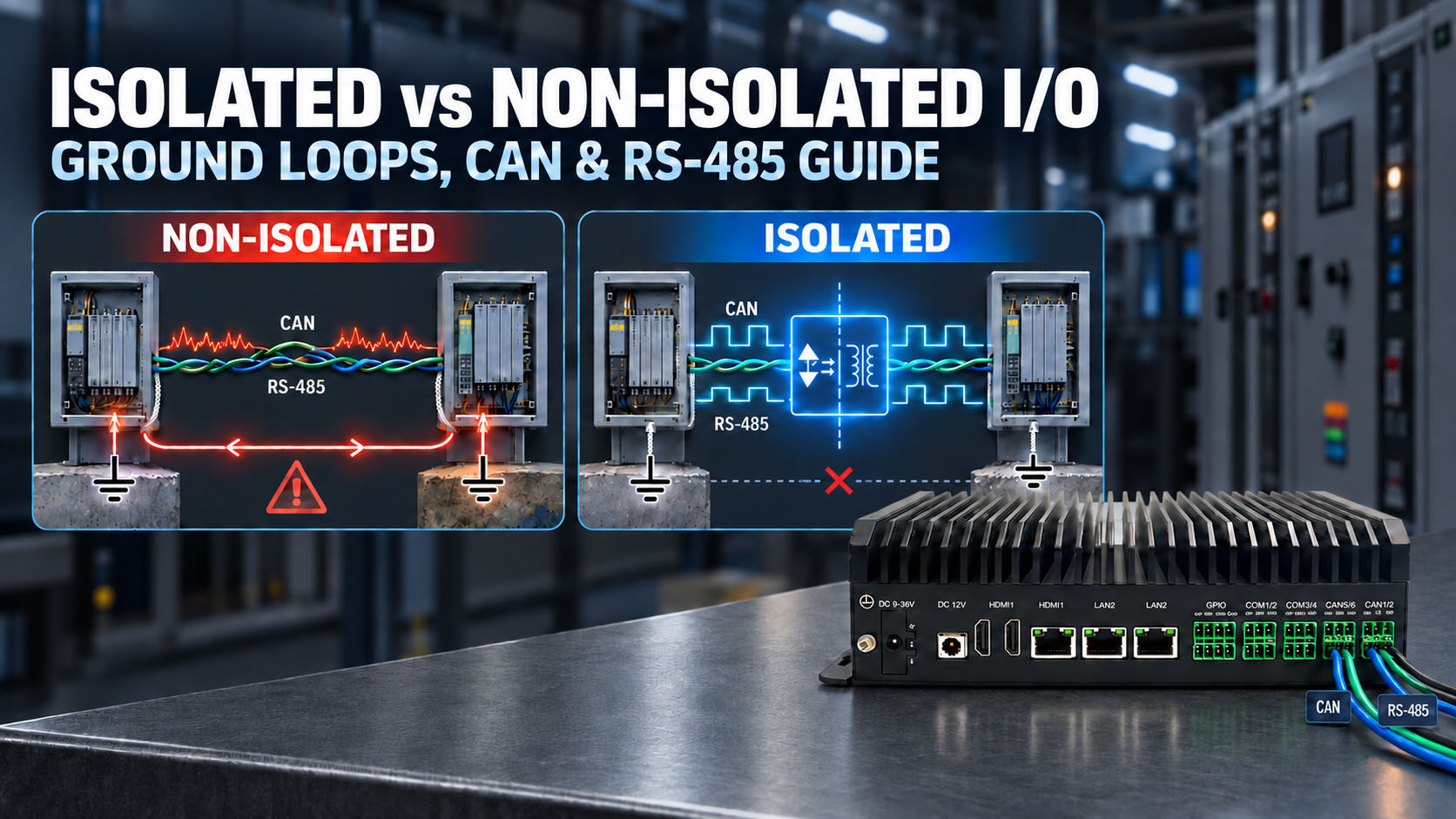
A galvanic barrier is an electrical firewall — it stops ground loops and surges at the interface before they cascade into the core.
BITECH Engineering Notes · ~8 min read
In short: Choose isolated I/O when a signal crosses between different ground references or touches the outside world — AGV/AMR motor-drive networks, long multi-axis cable runs, vehicle power buses, or high-EMI floors. Choose non-isolated I/O for clean cabinet installs with a unified ground plane, where you want lowest latency and cost. At BITECH, isolation isn’t a fixed feature you pay for whether you need it or not — on platforms like the AX-130BT it’s a configured option, fitted where the deployment demands it and left out where it doesn’t.
Start with the electrical topology: do the controller and field device share the same 0 V reference and power supply? Are signals staying inside one cabinet or crossing between cabinets? Cable length, nearby motors or VFDs, and vehicle or outdoor installation can all change the ground-potential and transient risk.
Use non-isolated I/O when the electrical reference is controlled and intentional. Evaluate galvanic isolation when the signal crosses separate ground domains or a harsher electrical environment.
The I/O stage is where an industrial computer meets the machine — and the machine is electrically hostile. A board that runs cleanly on a bench starts dropping CAN frames, logging phantom inputs, or failing outright once it’s wired to a motor drive, a solenoid bank, or a field sensor down a long cable. Almost often, that difference leads back to a decision made early: isolated or non-isolated I/O.
Isolated vs non-isolated I/O: quick answer
| Situation | Non-isolated I/O | Isolated I/O |
|---|---|---|
| Same cabinet and controlled 24 VDC supply | Often appropriate | Optional |
| Short wiring with a known common ground | Often appropriate | Optional |
| Separate cabinets or power supplies | Review ground topology | Often preferred |
| Long RS-485 or CAN field wiring | Possible with correct design | Often preferred |
| Vehicle or mobile equipment | Higher risk of ground shift | Strong reason to evaluate |
| VFDs, motors or contactors nearby | Depends on layout and protection | Strong reason to evaluate |
| Unknown ground potential | Risky | Usually preferable |
| High transient or surge environment | Protection still required | Isolation plus protection may be appropriate |
The key question is not simply whether the interface has isolation. Ask what is isolated from what, and what electrical problem the barrier is intended to solve.
What Galvanic Isolation Actually Does
A galvanic barrier removes the direct conductive connection between electrical domains. It breaks the direct ground-current path and helps limit fault propagation between the field side and host electronics.
Typical reasons include ground-potential differences, ground-loop current, separate power supplies, long field wiring, motors or VFDs, external machinery and separate vehicle power domains. Transient protection remains a separate design requirement.
Isolation is not the same as complete I/O protection
Adding an optocoupler or digital isolator does not automatically make an industrial input fully protected. A production interface may still need ESD and EFT protection, surge suppression, TVS devices, reverse-polarity protection, current limiting, filtering, correct grounding, shielding and wiring.
Galvanic isolation + transient protection + grounding + shielding + correct wiring = robust industrial interface
Isolation primarily separates electrical domains. It does not replace termination, shielding or transient protection, and it should not be treated as a universal cure for every electrical fault.
Ground Loops: The Main Problem Isolation Solves
Two connected devices can sit at different ground potentials because of supply impedance, cable length, load current or grounding layout. A non-isolated signal return can then carry current caused by that difference rather than by the intended data path. Symptoms include corrupted frames, false inputs, measurement error and damaged interface circuitry.
Galvanic isolation breaks that direct conductive ground-loop path. It does not guarantee immunity to every surge, nor does it remove the need to define cable shield termination and chassis bonding.
Differential signaling is not galvanic isolation
CAN and RS-485 use differential signaling to reject noise that appears similarly on both conductors. A standard non-isolated transceiver still operates within a defined common-mode range and maintains a conductive relationship with its local electrical domain. If the ground-potential difference becomes too large, communication can fail and the transceiver can be stressed beyond its limits.
Differential signaling
Improves noise rejection on the signal pair.
Galvanic isolation
Separates the electrical ground domains.
Isolation Is Not the Same as Complete I/O Protection
Isolation protects the boundary between electrical domains. Protection components protect interface circuitry from specific transient events. A robust interface may also require TVS devices, ESD protection, EFT/surge protection, filtering, current limiting, correct grounding, termination, cable and connector selection.
Galvanic isolation + transient protection + grounding + termination + correct cable and connector = robust industrial interface
Signal Isolation Also Requires an Isolated Power Domain
Breaking the signal path is not sufficient if the field-side circuitry remains powered through a shared conductive supply. Full galvanic separation normally requires both the data path and field-side power to cross an isolation barrier.
Signal path
MCU / CAN controller
↓ Digital isolation barrier
Field-side transceiver
↓ Field bus
Power path
Host power
↓ Isolated DC/DC
Field-side power
↓ Transceiver
Ask whether the implementation uses an isolated transceiver, a digital isolator plus transceiver, an isolated DC/DC converter or an integrated isolated power module.
Not All “Isolated I/O” Means the Same Thing
Always ask what is isolated from what. A datasheet label alone does not define the complete barrier architecture.
Port-to-system
One communication port is separated from system ground.
Group isolation
Several channels share one isolated field domain.
Channel-to-channel
Each channel has its own isolated domain.
What Does 4kV Isolation Actually Mean?
A 4kV isolation rating generally refers to dielectric withstand across the isolation barrier under a defined test condition. It does not mean the communication pins are rated for 4kV continuous working voltage or can directly withstand a 4kV surge.
| Specification | What It Tells You |
|---|---|
| Isolation withstand voltage | Short-duration dielectric strength across the barrier under a defined test |
| Working isolation voltage | Voltage permitted continuously across the barrier |
| Surge isolation voltage | Barrier capability under a defined surge test |
| Isolation classification | Functional, basic or reinforced isolation |
| Creepage / clearance | Physical insulation distance across and through the design |
| CMTI | Tolerance to fast common-mode voltage changes |
| Bus-fault voltage | Voltage the CAN or RS-485 pins can survive |
| ESD / EFT / surge | Interface-level transient immunity |
| Isolated power | Whether field-side power also crosses a barrier |
| Isolation topology | Port-to-system, group or channel-to-channel isolation |
“4kV isolated” is useful information, but it is not a complete I/O protection specification. Bus-fault voltage, ESD, EFT and surge ratings must be stated separately.
CAN: When Isolation Matters
Isolation becomes more useful when equipment uses separate power domains, the ground potential is uncontrolled, wiring leaves the machine, external equipment connects to the bus, high-voltage machinery is nearby or vehicle subsystems bridge separate electrical domains.
A local CAN network sharing a controlled vehicle ground may not require galvanic isolation. The decision follows the electrical domains, not the vehicle label alone.
RS-485: Isolation and Ground Potential
RS-485 is differential but still has a finite common-mode operating range. Isolation is a stronger choice when equipment is separately powered, ground offset may exceed transceiver limits, cables connect separate machines, or motors and VFDs create noisy grounding conditions.
RS-485 isolation helps prevent ground-current flow and keeps the field-side common-mode voltage within a controlled local domain.
Digital I/O: Isolation Has a Different Purpose
Digital inputs and outputs may connect PLC outputs, relays, solenoids, sensors, external controllers or 24V field rails. Isolation can separate field 24V from PC logic, reduce ground-loop current and limit fault propagation into host electronics.
Do not assume DIO isolation is architecturally identical to CAN or RS-485 isolation. Confirm input/output topology, common terminals, channel grouping, field-side supply and protection ratings.
Isolation Will Not Fix a Bad CAN or RS-485 Bus
Isolation cannot correct missing termination, excessive stub length, poor cable impedance, excessive node count, wrong bit timing, poor shield termination, incorrect RS-485 biasing or damaged transceivers.
A powered-off resistance near 60Ω is a useful first check for a conventional two-terminator high-speed CAN bus, but it does not prove topology, signal integrity or EMC performance. See the CAN 60Ω termination check.
Native CAN/CAN FD avoids an additional USB scheduling and bridge layer. The isolation barrier still contributes propagation delay, while reflection is mainly determined by cable impedance, topology, stub length and termination.
Does Isolation Add Latency?
Yes. The real question is whether it matters in the complete timing budget. Review isolator propagation delay, transceiver delay, pulse-width distortion, bit rate, cable length and controller timing together.
Non-isolated I/O is not inherently inferior; it is appropriate where the electrical ground domain is intentionally controlled and the architecture does not require isolation. Lower path delay is one trade-off, not the sole selection rule.
Isolated vs Non-Isolated I/O: Engineering Trade-Offs
| Engineering Factor | Isolated I/O | Non-Isolated I/O |
|---|---|---|
| Direct ground path | Broken across the barrier | Shared conductive reference |
| Ground-loop current | Reduced across the barrier | Possible |
| Separate ground domains | Strong fit | Requires common-mode control |
| Field-side power | Usually isolated for full separation | Shared |
| Transient protection | Still required | Still required |
| Propagation delay | Additional barrier delay | Lower component-path delay |
| BOM / PCB area | Higher | Lower |
| Design complexity | Higher | Lower |
| Long external wiring | Often preferred | Requires careful grounding |
| Controlled local wiring | Can be used | Often sufficient |
| Termination rules | Still apply | Still apply |
When Non-Isolated I/O Is Appropriate
- Devices intentionally share a controlled ground.
- Wiring remains local to one machine or cabinet.
- Common-mode voltage stays inside transceiver limits.
- Transient exposure is low and separately protected.
- BOM cost and PCB area matter.
- Isolation is not required by the system architecture.
When Isolated I/O Is a Stronger Choice
- Field wiring leaves the enclosure or connects remote equipment.
- Separate power supplies or uncertain ground potentials are involved.
- VFD, motor, contactor or solenoid noise is significant.
- External 24V I/O or high-voltage machinery connects to the computer.
- Vehicle subsystems cross electrical domains.
Vehicle Systems: Use Isolation for the Right Reason
Vehicle isolation becomes more important when the industrial PC bridges separate power domains, auxiliary equipment, chassis segments, external machinery or high-voltage systems. A local CAN network using a short harness within one ECU power domain and a controlled shared ground may not require galvanic isolation.
For the supply side of the design, see vehicle industrial PC power architecture and the vehicle-mounted industrial PC application.
30-Second Decision Tree
Does the signal cross another electrical ground domain?
├─ Yes → Is ground potential or transient exposure uncontrolled?
│ ├─ Yes → Strongly evaluate isolated I/O
│ └─ No → Check common-mode range and grounding
└─ No → Is wiring local inside one controlled machine?
├─ Yes → Non-isolated I/O may be sufficient
└─ No → Evaluate field-wiring and transient risk
If isolated, ask: What is isolated from what? Is field-side power isolated? What are the working and withstand voltages? What are the bus-fault, ESD, EFT and surge ratings?
What to Ask Beyond “4kV Isolated”
| Ask the Supplier | Why It Matters |
|---|---|
| What is isolated from what? | Defines the actual barrier topology |
| How was 4kV measured? | Distinguishes withstand from working voltage |
| Is field-side power isolated? | Confirms whether galvanic separation is complete |
| What is the working isolation voltage? | Defines continuous barrier stress |
| What is the bus-fault rating? | Defines pin-level overvoltage tolerance |
| What are the ESD, EFT and surge ratings? | Defines interface transient immunity |
| What is the CMTI? | Matters during fast common-mode events |
| Is isolation per port or grouped? | Determines shared-domain and fault-propagation behavior |
| What is the propagation delay? | Supports high-speed timing-budget review |
| Is a test report available? | Turns a marketing claim into reviewable evidence |
BITECH Platform Mapping
Selected BITECH industrial PC configurations provide isolated CAN, RS-485/RS-232 and digital I/O. Isolation voltage, topology and protection level depend on the product and project configuration.
| Application | I/O Direction | BITECH Direction |
|---|---|---|
| Local machine control | Controlled-ground CAN / RS-485 | Non-isolated or isolated per design |
| Factory equipment with VFDs or long wiring | Isolated CAN / RS-485 / DIO | Selected AX configurations |
| Vehicle or fleet system | Project-specific CAN isolation | Vehicle-configured industrial PC |
| Robotics or AGV | Isolation based on power and ground domains | AX / AE engineering review |
| High-voltage equipment interface | Galvanically isolated field boundary | Engineering review |
Six Details We Need for an I/O Isolation Review
- 1.Interface type
CAN, CAN FD, RS-485, RS-232, DI or DO - 2.Cable length
Total bus length, branch lengths and cabinet boundaries - 3.Connected equipment
Each device and its power source - 4.Ground relationship
Whether equipment intentionally shares the same ground - 5.Electrical environment
Expected noise, ESD, EFT and surge exposure - 6.Required qualification
Isolation requirement, standard or test report needed
Send us the electrical topology, not only the connector count.
Get an I/O isolation review
Not sure which interfaces to isolate? Send us the topology.
Isolation should follow the electrical topology, not a checkbox. Send BITECH engineering six project details and we'll tell you which interfaces should be isolated, which can stay non-isolated, and where shared grounding is acceptable — and the closest platform match.
Send six details
- Interface — CAN / CAN FD / RS-485 / RS-232 / DI / DO
- Field voltage — 5 V / 12 V / 24 V / other
- Power architecture — same PSU or separate supplies?
- Cable & cabinet layout — length and number of cabinets
- Electrical environment — nearby VFDs, motors, contactors, solenoids?
- Communication speed — baud rate or signal frequency
We review and return
- Which interfaces should be isolated
- Which interfaces can remain non-isolated
- Where shared grounding is acceptable
- Whether extra transient protection should be considered
- The closest BITECH platform match
Isolation matched to your electrical environment · isolated CAN/serial options · custom I/O from 100 units · 10-year lifecycle
Engineering FAQ
Isolated vs Non-Isolated I/O — Frequently Asked Questions
Is isolated I/O always better than non-isolated I/O?
No. Isolation adds cost, PCB area and design complexity. In a controlled cabinet where all devices intentionally share the same power and ground reference, non-isolated I/O may be completely appropriate. The decision should follow the electrical topology.
Is RS-485 already isolated because it uses differential signaling?
No. Differential signaling and galvanic isolation solve different problems. RS-485's differential pair rejects common-mode noise picked up along the cable, but the transceiver's own ground reference is still electrically connected to the rest of the system. If the ground-potential difference between two nodes exceeds the transceiver's common-mode voltage range, differential signaling alone will not protect the port — only a galvanic barrier (an isolated transceiver or isolated DC/DC domain) does that.
Does CAN need galvanic isolation?
It depends on the ground topology of the bus, not on CAN as a protocol. CAN is a multi-drop bus, so every node shares a reference with every other node on the segment. Isolation matters most when nodes are powered from different supplies, span long cable runs, or sit in electrically noisy environments — such as a vehicle chassis or a plant floor with variable-frequency drives — where ground-potential differences or induced noise can otherwise couple onto the bus.
Does galvanic isolation protect against surge?
Not by itself. Galvanic isolation and transient protection (ESD, EFT, surge) address different failure modes. Isolation breaks a continuous electrical path between two ground domains; surge protection clamps or diverts a short-duration high-energy transient. A port can be isolated and still need dedicated ESD/EFT/surge protection components, and vice versa — treating "isolated" as a synonym for "fully protected" is a common but incorrect assumption.
Do two PLCs need to share the same 0V?
Not if their I/O is properly isolated. Forcing two devices to share a 0V reference across a distance is exactly the condition that creates a ground loop: any potential difference between the two "0V" points drives an unwanted current through the shared reference conductor. Isolated I/O lets each device keep its own local ground reference, removing the shared low-impedance path that a ground loop depends on.
Are separate power supplies the same as isolated I/O?
No. Using two separate power supplies does not by itself create an isolated signal path — if their outputs still share a common return or chassis connection, the ground reference is still tied together. True I/O isolation requires the signal path itself to cross a galvanic barrier (an isolated transceiver, opto-isolator, or digital isolator) backed by an isolated DC/DC power domain on the isolated side, not just physically separate supplies.
Does isolated I/O create too much latency for industrial control?
In most industrial control applications, no. Isolator components add a small, fixed propagation delay to each signal edge, but for CAN, RS-485 and digital I/O running at typical industrial control bus speeds, that added delay is negligible relative to the bus timing budget. It becomes a real design consideration only in specific high-speed or tightly time-synchronized applications, where the isolator's datasheet propagation-delay figure should be checked explicitly against the system's timing margin.
Related Engineering Resources
Deeper reading on galvanic isolation, the buses it protects, and the BITECH platforms where the isolated/non-isolated choice is already built in.
Engineering guides
Industrial PC Galvanic Isolation Guide
The deep-dive this article points to — how isolated transceivers and isolated DC/DC power domains are engineered together.
Read the guide → EngineeringCAN Bus Isolation Engineering
A focused look at isolating CAN specifically — the bus this article names as most sensitive to ground-potential differences.
Read the guide → EngineeringCAN Bus 60Ω Termination Check
Isolation won't fix a bad bus — confirm termination is correct before troubleshooting further as a noise or isolation problem.
Read the guide → EngineeringPowering an Industrial PC in a Vehicle
Why isolation matters differently in a vehicle's power domain — the basis for this article's "Vehicle Systems" section.
Read the guide → EngineeringIndustrial PC Design Guide: EMC, Standards and Environmental Ratings
Where isolated I/O fits into the broader EMC and environmental qualification picture for an industrial platform.
Read the guide → SolutionVehicle-Mounted Industrial PC
A real deployment context where isolated CAN and RS-485 are typically required — dirty power, chassis ground bridging, long cable runs.
Explore the solution →Product platforms
AX-234BT vs AX-238BT
Both ship non-isolated CAN/serial by default — 4000V-isolated CAN and RS-485 are an equal ODM option on either. The real split is I/O philosophy: four displays and dual CAN, or Intel AMT and a third storage path.
Compare platforms → ProductAX-234BT — 4000V Isolated I/O, Vehicle-Rated
A shipping example of isolated I/O done for a real deployment — 4000V-isolated RS-232/422/485, validated for vehicle-mounted use.
View product → ComparisonAE-3588BT vs AE-3588LBT: Isolated vs Low-Latency
The same trade-off this article discusses in Section 13 ("Does Isolation Add Latency?"), applied to two edge-AI platform configurations.
Compare platforms →