
- Home /
- Conformal-coating
Conformal Coating for Industrial PCs
Materials, Thickness & Inspection
Conformal coating adds a thin protective layer to a PCB assembly to reduce the risk of moisture, contamination and electrical leakage. It complements enclosure sealing rather than replacing it.
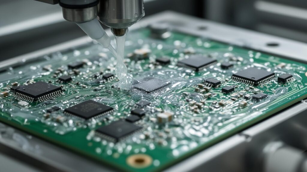
Coating performance depends on material selection, application control and finished-assembly validation.
Table of Contents
The Deployment Reality
Understanding Modern Industrial Computing Environments
Industrial computing systems are increasingly deployed in environments that were previously considered too harsh for electronics. Chemical processing plants expose systems to corrosive vapors. Offshore oil platforms subject equipment to constant salt spray and high humidity. Food and beverage facilities require regular washdown with aggressive cleaning agents. Smart infrastructure deployments place computing nodes in roadside cabinets and gantry-mounted enclosures exposed to vehicle exhaust and extreme temperature cycling.
In these environments, the traditional approach of specifying an IP65 or IP69K enclosure is no longer sufficient. The failure modes have shifted from direct water ingress to subtle, progressive damage from airborne contaminants that bypass conventional sealing. Understanding these failure mechanisms is essential for engineers responsible for system reliability in harsh deployments.
Corrosive vapors, high humidity, and thermal cycling create aggressive conditions for unprotected PCBs.
Salt spray exposure accelerates copper trace corrosion and creates dendrite growth between conductors.
Regular washdown with caustic cleaning agents and high-pressure water jets stress enclosure seals.
Environmental Stressors and Failure Modes
The Hidden Threats to Unprotected Industrial Electronics
The insidious nature of environmental failure modes is their latency. A system may pass all acceptance testing, operate normally for months, then suddenly fail. Post-mortem analysis reveals micro-shorts, corroded traces, or contamination-induced leakage currents—damage that accumulated gradually until a critical threshold was crossed. Understanding these stressors is the first step toward effective protection.
High Humidity (95%+ RH)
Moisture condensation on PCB surfaces creates conductive paths between traces. This causes intermittent failures that are extremely difficult to diagnose—systems may work normally at certain times of day but fail when temperature and humidity conditions change. In tropical climates or facilities with steam processes, sustained high humidity accelerates electrochemical migration between adjacent copper traces, eventually causing permanent short circuits.
Salt Spray and Marine Environments
Sodium chloride deposits are hygroscopic—they absorb moisture from the air and create corrosive electrolyte solutions on PCB surfaces. This accelerates copper trace corrosion and causes dendrite growth between adjacent conductors. In offshore wind installations and coastal deployments, salt accumulation follows ISO 9227 severity patterns, with electronics exposed to continuous corrosive attack that overwhelms conventional enclosure protection.
Corrosive Gases (H₂S, SO₂, Cl₂)
Industrial atmospheres often contain trace levels of corrosive gases. Hydrogen sulfide from oil/gas processing, sulfur dioxide from combustion, and chlorine from water treatment attack copper surfaces and solder joints, causing latent failures that appear weeks or months after deployment. These gases penetrate IP-rated enclosures through pressure equalization vents and cable gland tolerances, accumulating to corrosive concentrations over time.
Conformal Coating vs IP-Rated Enclosure
Different protection layers address different failure paths
| Protection Method | Main Function | Typical Role |
|---|---|---|
| IP-rated enclosure | Keeps external dust and water away from electronics | Primary environmental barrier |
| Conformal coating | Adds PCB-level moisture and contamination protection | Secondary board-level protection |
| Potting / encapsulation | More complete component encapsulation | Severe-environment or mechanical protection |
An IP-rated enclosure remains the first barrier. Coating can add PCB-level protection if moisture, contamination or condensation reaches the assembly. Neither layer should be used to overstate the capability of the other.
IPC-CC-830C: What the Standard Does — and Does Not — Mean
IPC-CC-830C addresses conformal-coating material qualification, conformance and standardized property testing. Qualified material is not the same as a qualified finished industrial PC.
| Standard | Main Role | What It Does Not Prove |
|---|---|---|
| IPC-CC-830C | Coating material qualification and conformance | Finished-product field reliability |
| IPC-HDBK-830A | Design, selection and application guidance | Product certification |
| IPC-A-610J | Assembly and workmanship acceptance | Coating chemistry qualification |
What it supports
Material qualification, material conformance and standardized coating-property testing.
What it does not prove
IP rating, corrosion life, complete product qualification or finished-PC performance in the target machine.
Which Coating Chemistry Should You Choose?
Select from the deployment environment, not the chemistry name alone
| Chemistry | IPC Type | Main Engineering Consideration |
|---|---|---|
| Acrylic | AR | Easy rework and general moisture protection |
| Polyurethane | UR | Stronger chemical and solvent resistance; harder rework |
| Silicone | SR | Flexible; suited to wider thermal cycling depending on material |
| Epoxy | ER | Strong barrier; difficult to rework |
| Parylene | XY | Vapor-deposited thin coating requiring a specialized process |
| Ultra-thin | UT | Application-specific thin-film protection |
| Styrene block co-polymer | SC | Specialized material option |
Cure methods
Air drying, moisture curing, thermal curing, UV curing and dual-cure systems describe how a coating hardens.
Inspection aids
Fluorescent tracer, UV inspection, visual inspection and dry-film measurement support process control. They are not coating chemistries.
Coating Thickness Is Material- and Process-Specific
Required dry-film thickness depends on chemistry, supplier specification, application method and end-use environment. A 26–38 μm range must be described as a controlled target for a selected BITECH process when confirmed—not as a universal IPC optimum.
What Should Not Be Coated
Specify complete coverage of designated coating areas, with controlled keep-out zones for contacts, connectors and thermal interfaces.
BITECH Application Process: Mask → Coat → Cure → Inspect
BITECH can provide project-specific coating options on selected platforms. Chemistry, masking, application, inspection and thickness controls are defined by the project requirement.
How UV Inspection and Thickness Measurement Work Together
UV inspection can help verify
- Coating presence
- Missing designated areas
- Obvious voids
- Designated-area coverage
UV inspection alone does not prove
- Dry-film thickness
- Adhesion or cure completeness
- A pinhole-free barrier
- Long-term environmental reliability
UV inspection verifies coating presence across designated areas; thickness and process quality are verified separately according to the manufacturing control plan.
Humidity, Salt and Chemical Environments Need System-Level Validation
Together, these conditions increase leakage, corrosion and electrochemical-migration risk.
Marine and salt-laden environments
Validate chemistry and complete-system protection against the required environmental plan. Salt-mist testing is an accelerated comparative method, not a direct prediction of field service life.
Chemical and washdown environments
The enclosure remains the first barrier. Select coating chemistry for compatibility with cleaning agents, oils, solvents or process chemicals that may reach the PCB.
Where Conformal Coating Is Commonly Specified
Roadside / Traffic
Humidity, condensation, exhaust contamination and temperature cycling. Use enclosure protection, suitable coating and project-specific environmental validation.
Marine / Coastal
Salt-laden atmosphere and high humidity. Use enclosure protection, suitable coating and project-specific environmental validation.
Food / Process
Washdown, cleaning chemicals and condensation. Use enclosure protection, suitable coating and project-specific environmental validation.
Agricultural / Heavy Equipment
Dust, moisture, fertilizer contamination and vibration. Use enclosure protection, suitable coating and project-specific environmental validation.
Conformal Coating vs Potting / Encapsulation
| Feature | Conformal Coating | Potting / Encapsulation |
|---|---|---|
| Thickness | Thin | Thick |
| Reworkability | Moderate to high, chemistry dependent | Low |
| Weight | Low | Higher |
| PCB accessibility | Better | Poor |
| Moisture barrier | Good, chemistry dependent | Strong |
| Mechanical support | Limited | Stronger |
| Heat-transfer impact | Process-specific | Can be significant |
| Typical use | Industrial PCB protection | Severe-environment encapsulated electronics |
The two methods are not interchangeable. Potting provides more complete encapsulation but greatly reduces serviceability.
How to Specify Conformal Coating in an Industrial PC RFQ
| RFQ Item | Example Input |
|---|---|
| Deployment environment | Indoor / outdoor / vehicle / marine |
| Humidity and condensation | %RH plus Yes / No condensation risk |
| Salt exposure | None / coastal / marine |
| Chemical exposure | Cleaning agent / oil / solvent / process chemical |
| Operating temperature | Minimum and maximum temperature |
| Enclosure IP level | Required system-level rating |
| Rework requirement | High / medium / low |
| Expected service period | Target years and maintenance interval |
| Annual quantity | Prototype and production volume |
| Required test standard | Standard, severity, cycle, duration and pass criteria |
| Chemistry preference | AR / UR / SR / open to engineering review |
| Thickness target | Project-specific |
| Inspection method | UV / visual / dry-film thickness |
| Masking and keep-outs | Drawing or project-specific list |
Specify the environment first, then choose the coating. Do not start from the chemistry name alone.
Get a coating engineering review
Need a conformal-coating specification for your industrial PC?
Send BITECH your deployment environment, humidity, condensation risk, salt exposure, chemical exposure, operating temperature, enclosure requirement, rework needs and expected lifecycle. We can review the coating chemistry, masking, thickness and validation plan.
Send us the environment
- Deployment environment & humidity
- Condensation, salt or chemical exposure
- Operating temperature range
- Enclosure IP requirement
- Rework needs & expected service period
- Required test standard, if any
We review and return
- Coating chemistry recommendation (AR / UR / SR / other)
- Masking & keep-out plan
- Thickness target for the selected process
- Inspection method (UV / visual / thickness)
- An honest answer if coating isn't the right call
If conformal coating is unnecessary for the deployment, we'll say so. If it is required, the coating process should be matched to the actual environment rather than selected from a generic checklist.
Conformal Coating · IPC-CC-830C
Frequently asked questions
-
It helps reduce PCB exposure to moisture, contamination, condensation and related electrical leakage or corrosion risks.
-
No. Waterproofing and IP rating depend on the complete enclosure, connectors, seals and mechanical design.
-
It is a qualification/conformance standard for conformal-coating materials. It does not by itself certify the finished industrial PC for a specific environment.
-
There is no universal value. Thickness depends on coating chemistry, supplier specification, process and end-use environment.
-
Not universally. If BITECH uses 26–38 µm as a controlled production target, it is described as a BITECH process target, not an industry-wide optimum.
-
Usually no. Connectors, contacts, sockets, test points and other defined keep-out areas are typically masked as required by the design.
-
No. UV inspection helps verify coating presence and coverage. Thickness must be measured separately.
-
It depends on the environment, chemical exposure, temperature, rework needs and selected material properties.
-
Not universally. Conformal coating is thinner and more serviceable; potting provides more complete encapsulation but is harder to repair.
-
No. Service life depends on the complete product design, environment, coating material, process quality and validation.
Related engineering & platforms
Coating is one layer of a complete environmental design
Conformal coating works alongside enclosure sealing, power protection and I/O isolation — not instead of them. These guides and platforms cover the rest of the environmental design.