
How to Power an Industrial PC in a Vehicle (9–36V, Ignition, Protection)
A vehicle’s DC supply is one of the most abusive environments an embedded computer will ever see. Here’s what it actually takes: 9–36V wide input, ignition control, battery protection, and transient protection to ISO 7637-2 / ISO 16750-2.
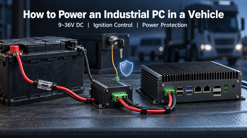
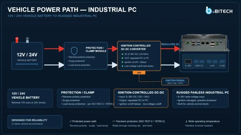
A correct in-vehicle power architecture: battery → protection → ignition-controlled DC-DC → clean rails for the PC.
Table of Contents
Powering an industrial PC in a vehicle takes more than a 12V wire. A vehicle’s DC supply is electrically hostile — load-dump surges, cranking dips, reverse polarity and switching transients that destroy consumer power stages. A proper in-vehicle PC uses a 9–36V wide-range input (covering 12V cars and 24V trucks), ignition sensing with timed on/off delays, low-voltage battery protection, and transient protection to ISO 7637-2 / ISO 16750-2.
Get those four right and the computer boots with the key, survives the alternator, and never flattens the battery. A PC that ran perfectly on a bench but reboots on cranking or corrupts its filesystem overnight doesn’t have a software problem — it has a power problem.
Why you can’t just wire a PC to the battery
The “12V” or “24V” label on a vehicle battery describes its resting voltage, not what appears on the wire. In practice the supply swings widely and violently:
- Engine cranking drops the bus voltage sharply for tens of milliseconds as the starter draws hundreds of amps. A PC wired naively brown-outs and reboots every start.
- Load dump — the alternator charging while the battery connection is suddenly lost — produces the highest-energy transient in the vehicle, historically tens to hundreds of volts.
- Switching inductive loads (relays, solenoids, motors, wipers) inject fast voltage spikes onto the supply lines.
- Reverse polarity happens whenever the battery or a jump lead is connected backwards.
- Sustained overvoltage appears from a 24V jump-start on a 12V system or a failed regulator.
A consumer PSU expects a clean, regulated rail. Feed it a vehicle bus and it’s only a matter of time. A real in-vehicle power stage is engineered to absorb, clamp, or ride through every one of these.
The 9–36V wide-input range
The first specification to get right is the input range. Passenger cars and vans run nominal 12V systems; trucks, buses, construction and agricultural equipment run 24V. A single 9–36V wide-input design covers both nominal systems and their real-world extremes — the low end holds the PC up through cranking sag, and the high end tolerates charging voltage and moderate overvoltage.
Buying a 9–36V unit means one SKU deploys across a mixed fleet of 12V and 24V vehicles, and the same computer survives the low-voltage cranking dip that a fixed 12V-only supply would brown out on. If a vendor only offers a narrow 12V input, it was not designed for vehicles.
9–36V Does Not Guarantee Cold-Crank Ride-Through
During engine start, supply voltage can temporarily fall below the computer’s normal input range. Cold-crank behavior must be validated separately against the required starting profile.
Depending on the application, the design may require hold-up energy, buck-boost regulation, an energy buffer or controlled ignition sequencing. The acceptable functional result may be continuous operation, a controlled reboot, delayed boot, or safe shutdown and restart.
Ignition control: powering on and off with the key
A vehicle PC must behave like every other device on the dashboard: on with the key, off with the key — but gracefully, and without draining the battery. That’s what ignition control (ignition sensing) provides, using the vehicle’s ACC/IGN line as a signal input separate from the main power feed.
Timed power-on delay
The PC waits a configurable interval after ignition-on before booting, so it doesn’t start during the cranking dip.
Timed power-off delay
When the ignition turns off, the PC keeps running for a configurable period, then triggers a graceful OS shutdown rather than a hard power cut.
Anti-drain
Because shutdown is clean and the delay is bounded, the PC stops drawing from the battery when the vehicle is parked.
Programmable on/off delays matter: a fleet-telematics box might shut down 30 seconds after key-off, while a surveillance or cold-chain logger might stay alive for hours. Both need the delay to be a setting, not a fixed value.
Protecting Against Load Dump, Reverse Polarity and Fast Transients
Load dump
Load dump is a relatively long overvoltage event compared with fast transient pulses. The protection stage must withstand or clamp the specified waveform without overstressing downstream electronics. The required level depends on the vehicle voltage system and project test condition.
Fast conducted transients
ISO 7637-2 addresses positive spikes, negative spikes and switching transients conducted along 12V or 24V supply lines. A claim should identify the pulse, severity and tested configuration.
Reverse polarity
The input should define its behavior when the supply is reversed. Diode, ideal-diode MOSFET or protected high-side methods may be used, but protection should not be claimed without a validated test condition.
ISO 16750-2 vs ISO 7637-2: What Each Standard Covers
| Standard | Scope |
|---|---|
| ISO 16750-2:2023 | Electrical loads for road-vehicle electrical/electronic equipment, including supply voltage, overvoltage, voltage drops, starting profile, load dump and reverse voltage. |
| ISO 7637-2:2011 | Conducted electrical transient tests on 12V and 24V supply lines. |
Load dump: Test A / Test B, not the primary label Pulse 5a / 5b
Older automotive references often use Pulse 5a and Pulse 5b. In current ISO 16750-2 terminology, load dump is described using Test A / Test B conditions.
A serious specification identifies the test condition, waveform or pulse, severity, system voltage, configuration tested and functional result—not the standard number alone.
Battery protection: don’t flatten the vehicle
Ignition control handles the normal park cycle, but a robust design adds a second safety net: low-voltage protection (a battery guard). If the battery voltage falls below a set threshold — a vehicle left unused for days, a marginal battery — the PC shuts down and disconnects rather than discharging the battery to the point the vehicle won’t start. On a fleet, “the van won’t start because the logger drained the battery” is a call nobody wants, and a configurable undervoltage cutoff prevents it.
The power path, end to end
Put together, a correct in-vehicle power architecture looks like this, in order from the battery inward:
- 1
Battery / vehicle bus
9–36V, dirty and unregulated
- 2
Protection front-end
Reverse-polarity block, load-dump clamp, overvoltage and transient suppression (ISO 7637-2 / 16750-2)
- 3
Ignition-controlled switch
Reads the ACC/IGN line; applies power-on and power-off delays
- 4
Wide-range DC-DC regulation
Converts the surviving 9–36V into clean rails for the PC
- 5
Low-voltage cutoff
Disconnects before the battery is over-discharged
- 6
The industrial PC
Now sees a clean, protected, ignition-managed supply
Everything before the final step is the difference between a computer that survives a vehicle and one that merely runs on a bench.
What to Ask an In-Vehicle PC Supplier
| Ask the supplier | Weak answer | Better evidence |
|---|---|---|
| Input voltage | “9–36V” | Continuous operating range plus startup-profile behavior |
| Cold crank | “Wide voltage” | Starting-profile test and functional result |
| Load dump | “Automotive protected” | ISO 16750-2 Test A / Test B condition |
| Fast transients | “ISO protected” | Specific ISO 7637-2 pulses tested |
| Reverse polarity | “Protected” | Test voltage, duration and behavior |
| Ignition | “ACC supported” | Configurable on/off timing and shutdown sequence |
| Battery drain | “Auto shutdown” | Cutoff, reconnect threshold and off-state current |
| Power input | “Vehicle ready” | Test report or defined electrical qualification |
| Connector | “DC terminal” | Locking automotive or industrial connector |
| Functional result | “Pass” | Stayed running, rebooted, shut down safely or recovered |
The useful answer is not “automotive grade.” The useful answer is the tested electrical condition and functional result.
Vehicle Power Testing Is Not the Same as E-Mark / UN R10
ISO 16750-2 and ISO 7637-2 address electrical loads and conducted transients. Passing those tests does not automatically mean a device has UN ECE R10 or E-Mark approval. Power-transient qualification and regulatory EMC approval are separate requirements for the exact tested configuration.
How BITECH Configures Vehicle Power
Selected BITECH vehicle configurations are available with wide-voltage DC input, ignition control, transient-protected power stages and isolated vehicle or industrial interfaces. Final power and I/O configuration is defined per project and validated against the intended vehicle environment.
| Requirement | BITECH direction |
|---|---|
| Standard vehicle or fleet control | Vehicle-configured AX platform |
| Multi-camera mobile AI | AE-NJ60BT / Jetson direction |
| High-performance RTX workload with airflow available | AE-760EBT |
| Sustained high-load RTX with an airflow-constrained compute zone | AE-960EBT engineering review |
Power architecture must be validated per vehicle project. Do not assume the compute platform alone defines vehicle readiness.
Get a vehicle power review
Bench-tested isn't vehicle-proven. Send us the electrical environment.
Tell BITECH engineering the vehicle bus voltage, duty cycle and mounting environment, and we'll confirm the power architecture — input range, transient protection, ignition timing and low-voltage cutoff — before a cranking dip or a load dump finds the gap on your bench-tested unit.
Send us the electrical environment
- Vehicle bus voltage (12V car / 24V truck / other)
- Alternator size & known load-dump history
- Ignition-off behavior needed (delay, hard cut)
- Parked duty cycle (days unused, battery type)
- CAN / RS-485 devices sharing the same bus
- Ambient temperature & vibration environment
We review and return
- Input range & transient protection to ISO 7637-2 / 16750-2
- Ignition timing & low-voltage cutoff configuration
- Isolated CAN / RS-485 recommendation, if needed
- Connector recommendation (locking Phoenix vs standard)
- Closest BITECH platform & a sample configuration
9–36V wide input · ISO 7637-2 / ISO 16750-2 tested · optional 4000V isolated CAN & RS-485 · OEM/ODM, 10-year lifecycle
Vehicle Power · 9–36V
Frequently asked questions
-
Because “12V” describes the battery's resting voltage, not what actually appears on the wire. A vehicle's DC supply is electrically hostile — cranking dips, load-dump surges, reverse polarity and switching transients that a consumer power stage isn't built to survive.
-
A 9–36V wide-range DC input, which covers both 12V car electrical systems and 24V truck/commercial-vehicle systems from a single power stage — no external voltage regulator needed.
-
Engine cranking drops the bus voltage sharply for tens of milliseconds as the starter motor draws hundreds of amps — a “cranking dip” the power stage has to ride through without the PC rebooting.
-
Load dump is the transient that occurs when the alternator is charging and the battery connection is suddenly lost. It's the highest-energy disturbance on a vehicle bus, defined by ISO 16750-2 (Pulses 5a/5b), and without a power stage designed to clamp or absorb it, load dump can destroy downstream electronics.
-
Yes. Load-dump energy scales with system voltage, so a 24V commercial-vehicle system produces a substantially higher-energy load dump than a 12V car — a power stage rated only for 12V duty is not automatically safe on a 24V truck.
-
Two. ISO 7637-2 covers electrical transients conducted along the supply lines (fast spikes from switching inductive loads), and ISO 16750-2 covers electrical loads including load dump, overvoltage, reverse polarity and cranking.
-
It adds a timed power-on delay so the PC boots after cranking finishes, and a timed power-off delay so that when the key turns off, the PC performs a graceful OS shutdown instead of a hard power cut — protecting the filesystem and preventing the computer from draining the battery while parked.
-
Ignition control handles the normal park cycle, but a battery guard is a second safety net: if the battery voltage falls below a set threshold — a vehicle left unused for days, a marginal battery — the PC shuts down and disconnects, rather than discharging the battery to the point the vehicle won't start.
-
In order from the battery inward: reverse-polarity block → load-dump clamp → overvoltage/transient suppression (tested to ISO 7637-2 / ISO 16750-2) → ignition-controlled DC-DC → clean rails for the PC. Skipping any stage is the difference between a computer that survives a vehicle and one that merely runs on a bench.
Compare & go deeper
Platforms built for the electrical environment you described
These BITECH platforms already ship with 9–36V wide-range input, transient protection and optional isolated fieldbus — and the guides go deeper on the CAN/RS-485 side of a mobile deployment.