
Industrial PC Design Guide: Thermal, Power, EMC & Lifecycle Engineering
An industrial PC is not defined only by the processor or enclosure. Reliable deployment depends on how heat is moved, power disturbances are handled, interfaces are protected, environmental exposure is controlled, and the hardware platform is maintained over its lifecycle.
A specification is only useful when it is tied to the exact configuration and validated under the intended operating condition.
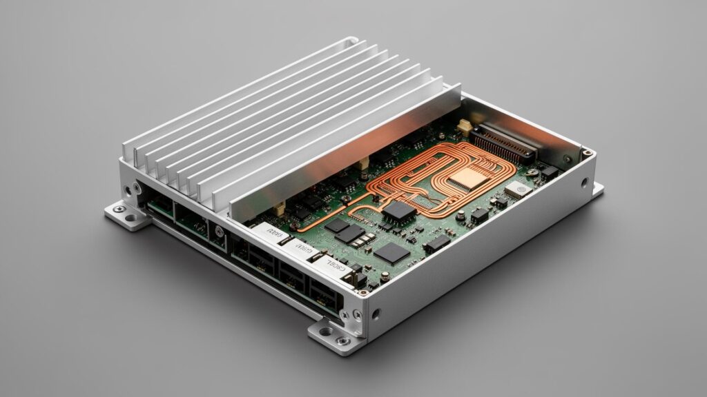
Thermal architecture, power input, EMC, isolation, coating, connectors and lifecycle strategy should be validated together rather than treated as independent checkbox specifications.
Thermal
Move sustained heat to ambient
Power
Regulate, protect and recover
EMC / Isolation
Control noise and ground paths
Environmental
Protect enclosure, PCB and connectors
Lifecycle
Control BOM, revisions and supply
Validation
Document conditions and evidence
Table of Contents
Thermal Architecture: Move Heat from Silicon to Ambient
A thermal design is a complete heat path. The interface, spreader, chassis or radiator and surrounding environment all affect whether processor performance remains stable.
Passive vs Active Air vs Remote Liquid Cooling
| Architecture | Typical use | Main constraint |
|---|---|---|
| Passive conduction | Low to moderate sustained heat | Chassis area and ambient temperature |
| Heat pipe + chassis conduction | Higher localized CPU heat | Heat spreading and contact resistance |
| Active air cooling | High sustained CPU/GPU workload | Clean, dependable airflow |
| Remote liquid cooling | High GPU load or airflow-constrained compute zone | Cold plates, coolant loop and remote radiator |
Thermal Design Is Not Defined by TDP Alone
Peak silicon power is only one input. Sustained CPU package power, GPU TGP, workload duty cycle, ambient temperature, enclosure volume, heat-spreader geometry, orientation, airflow, contamination and allowable component temperature determine the cooling architecture together.
6061-T6 aluminum
Typical thermal conductivity is approximately 167 W/(m·K), depending on alloy condition and source data. Do not use 237 W/(m·K) as a 6061-T6 value.
Thermal interface material
Qualified grease, phase-change material or another project-specific TIM is selected by power density, contact materials, serviceability and lifecycle requirements. Product lifecycle and TIM service life are separate questions.
Extended-temperature claims are configuration-specific
Selected configurations can be engineered and validated for extended-temperature operation. Published ranges should identify the CPU, storage, memory, power and thermal configuration tested, together with cold boot, hot operation, workload duration, chamber condition, temperatures, sustained clocks and functional result.
Power Architecture: Operating Range, Protection and Isolation
Wide-input voltage is only one layer of industrial power design. Selected BITECH platforms support 9–36V wide DC input; this is not a blanket specification for every platform.
Wide-voltage input does not equal vehicle qualification
Vehicle deployments require separate crank, load-dump, reverse-polarity and transient qualification beyond the continuous input range. A 60V OVP value alone is not proof of load-dump capability; behavior should be tested against the required ISO 16750-2 or project-specific condition.
Power isolation is not signal isolation
Galvanically isolated DC input is available on selected configurations where the architecture requires it. Topology and withstand voltage depend on the chosen DC/DC design and must not be inferred from CAN, RS-485 or digital-I/O isolation ratings.
How to Power an Industrial PC in a VehicleEMC & Interface Integrity
Industrial systems can face ESD, EFT, surge, conducted and radiated RF, ground-potential differences, motor or VFD noise, long cables and shared grounding paths. The response may combine enclosure bonding, filtered I/O, transient suppression, common-mode filtering, interface isolation, shield termination and connector selection.
Conducted immunity
IEC 61000-4-6 is a conducted RF immunity test. Its test level is expressed in volts, not volts per meter.
Radiated immunity
IEC 61000-4-3 covers radiated RF immunity and uses V/m.
Shielding is more than wall thickness
Metal construction, conductive bonding and controlled apertures can form part of the shielding strategy. Actual performance also depends on seams, panel bonding, ventilation openings, gaskets, cable shields, connector grounding and verified surface treatment. Ordinary anodize should not be assumed to provide electrical continuity.
Separate EMC from mechanical and environmental testing
MIL-STD-810 methods address selected mechanical and environmental stresses, not EMC. Any claim should name the exact method, procedure, configuration and result. EMC targets also depend on product family, port and project; selected platforms may be validated against industrial immunity standards such as EN IEC 61000-6-2.
Interface isolation and CAN diagnosis
Selected configurations provide isolated CAN, RS-485/RS-232 and digital I/O. Voltage and topology depend on the circuit. A powered-off CAN resistance near 60Ω is only a first check for two 120Ω endpoint terminators—it does not prove topology, stub length, common-mode margin, bit timing or EMC performance.
Environmental & PCB Protection
Environmental protection is layered rather than created by one coating or one IP rating. PCB-level protection may include conformal coating, selective masking and interface isolation. Chemistry and thickness should follow the deployment environment and drawing.
| Protection layer | Main role |
|---|---|
| Enclosure | External dust and water barrier |
| Gaskets / connectors | Ingress control at openings |
| Conformal coating | PCB-level moisture and contamination protection |
| Isolation | Electrical boundary between selected interfaces |
| Thermal design | Controls heat in sealed or harsh environments |
Where coating qualification is specified, use the current IPC-CC-830C revision and define the material, process, masking, inspection and acceptance criteria.
Engineer’s Guide to Conformal CoatingLifecycle Engineering: BOM, PCN and Platform Continuity
Long-lifecycle hardware is a supply-chain and configuration-management problem, not only a processor-roadmap problem. Controlled BOM, silicon roadmap, memory and storage lifecycle, modular carrier design, PCN tracking, replacement qualification, last-time-buy planning, BIOS control and mechanical continuity all contribute.
BITECH targets long platform availability through controlled BOM, modular architecture and supplier lifecycle planning. Availability should be stated by SKU and underlying silicon roadmap rather than as one universal guarantee.
Lifecycle Management and PCN ControlValidation: A Specification Is Not Evidence Until It Is Tested
A specification becomes engineering evidence only when the test condition, exact configuration and pass criteria are documented.
| Design claim | Required evidence |
|---|---|
| Wide temperature | Chamber test with exact CPU, memory, storage and power configuration |
| Sustained GPU performance | Temperature, clock and workload logs through thermal equilibrium |
| EMC immunity | Laboratory report identifying standard, level, ports, configuration and result |
| Vehicle power | Required ISO waveform or project-specific transient and crank conditions |
| Interface isolation | Topology review plus dielectric withstand or isolation test |
| Conformal coating | Material/process record, inspection and relevant environmental test |
| CAN reliability | Resistance check plus electrical and communication validation |
| Lifecycle | Controlled BOM, PCN workflow and supply policy |
From Engineering Design to Field Deployment
Industrial PC design must go beyond specifications. Thermal performance, power protection, interface reliability, and environmental durability need to be evaluated under real operating conditions. Explore our real-world industrial computing case studies to learn how BITECH applies these engineering principles in customer deployments.
How BITECH Maps Engineering Requirements to Platforms
Final platform selection should be workload-first and deployment-first. These directions start the review; they do not replace configuration-level validation.
| Engineering need | BITECH direction |
|---|---|
| Fanless general industrial control | AX Series |
| Machine vision / AOI | AX or AE, selected by workload |
| High sustained RTX AI | AE-760EBT |
| Airflow-constrained high-load AI | AE-960EBT |
| Mobile / robotic AI | AE-NJ60BT / Jetson |
| Vehicle integration | Vehicle-qualified power configuration |
| Humidity or contamination | Coating + enclosure review |
| Long lifecycle | Controlled BOM + modular strategy |
Get a validated configuration, not a spec sheet
A specification is not evidence until it's tested against your configuration.
Send BITECH your workload, deployment environment and interface requirements. We review thermal, power, EMC, protection and lifecycle together as one system — and return the test conditions and evidence behind the numbers, not a marketing figure lifted from a different configuration.
Send us the deployment
- CPU/GPU workload & sustained duty cycle
- Ambient temperature & enclosure constraints
- Power source (mains / DC / vehicle) & voltage range
- Interfaces requiring isolation (CAN, RS-485, digital I/O)
- EMC / environmental standards required
- Expected lifecycle & annual volume
We review and return
- Thermal architecture matched to sustained load
- Power protection & isolation recommendation
- Relevant EMC / environmental standard and test plan
- Lifecycle commitment tied to the actual SKU
- Documented test conditions behind every number we give you
Every claim on this page is tied to a configuration and a test condition — ask for the documentation behind any number before you design around it.
Engineering FAQ
Frequently asked questions
Common questions from senior engineers reviewing thermal, power, EMC, protection and lifecycle requirements for industrial PC deployment.
-
It depends on the exact configuration. Fanless platforms span low-power Atom-class SoCs up to Core i5/i7 U-series processors with configurable PL1/PL2 turbo, cooled through CFD-optimized heatsinks, heat pipes and thermal-interface selection matched to the power density. A TDP figure is only meaningful tied to the specific CPU, enclosure and validated ambient condition — not quoted as a platform-wide number.
-
4000V optical isolation creates a galvanic barrier between power input and system logic, intended to stop ground-potential differences and switching noise (motor PWM, VFD transients) from corrupting CAN, RS-485 or Ethernet signals. 4000V is a withstand voltage verified by a short dielectric test — not a continuous working voltage, and power isolation is a separate design from signal isolation; one should not be inferred from the other's rating.
-
An IP65 enclosure is the primary barrier against external dust and water jets, but internal condensation can still form during temperature cycling if humid air enters through breather vents. Conformal coating is a separate, PCB-level layer against moisture, contamination and condensation. For washdown or coastal deployments the two are typically used together, not as substitutes for each other.
-
The current revision is IPC-CC-830C, used for material qualification and conformance testing. It qualifies the coating material and process — it does not by itself certify the finished industrial PC for a specific environment, and thickness targets are process- and chemistry-specific rather than one universal figure.
-
Availability tracks the underlying silicon roadmap and BITECH's own BOM control — it is stated per SKU, not as one universal guarantee across every platform. All platforms run on a controlled BOM with a defined PCN notice period and a last-time-buy window before any change takes effect; ask for the specific lifecycle commitment tied to the SKU under consideration.
-
Selected platforms are validated against industrial immunity standards such as EN IEC 61000-6-2, which bundles tests including ESD (IEC 61000-4-2), EFT (IEC 61000-4-4), surge (IEC 61000-4-5), conducted RF immunity (IEC 61000-4-6, expressed in volts) and radiated RF immunity (IEC 61000-4-3, expressed in V/m). Mixing up those two units is a common and meaningful error — any EMC claim should name the exact standard, level, port and test configuration, not a bare number.
-
No. MIL-STD-810 methods address selected mechanical and environmental stresses — shock, vibration, temperature cycling — not EMC. A shock or vibration claim should name the exact method, procedure, configuration and result, and should never be read as evidence of electromagnetic compatibility.
-
Standard and extended-temperature configurations exist, but the achievable range depends on the exact CPU, storage, memory and power configuration selected — it is not one number that applies across every platform. A published extended-temperature range should be backed by chamber verification identifying the tested configuration, cold-boot and sustained-load conditions, and the functional result, not quoted as a standalone spec.
-
A correctly terminated CAN bus has two 120Ω terminators, one at each end; measured powered-off, they read roughly 60Ω in parallel. A reading near 120Ω suggests a missing terminator; near 40Ω suggests an extra one. This is a first-pass check only — a resistance reading near 60Ω does not by itself prove correct topology, stub length, common-mode margin, bit timing or EMC performance, all of which need separate validation.
-
No. Wide-input voltage is only one layer of vehicle power design. Vehicle deployments also require separate qualification for cranking dips, load dump, reverse polarity and transients — typically to ISO 16750-2 or a project-specific condition. An overvoltage-protection rating alone is not proof of load-dump capability.
How BITECH maps engineering requirements to platforms
Start with the workload, then validate the configuration
Final platform selection should be workload-first and deployment-first. These directions start the review; they do not replace configuration-level validation.