
Engineering Pillar Guide

Galvanic Isolation in Industrial PCs: CAN, RS-485, DIO & Isolation Ratings

How the barrier works—and what the ratings actually mean

Galvanic isolation breaks the direct conductive path between field-side wiring and host electronics. It is commonly used to manage ground-potential differences, ground-loop current and fault propagation across industrial interfaces.
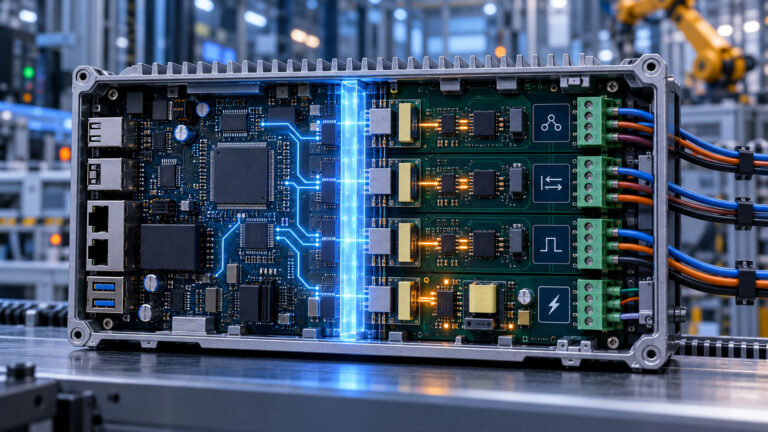
Galvanically Isolated Industrial Control ModuleThe barrier, field-side supply and protection network must be reviewed as one interface architecture.

Table of Contents

Quick answer

Always ask: what is isolated from what, how the field side is powered, and what the voltage rating actually represents.

An isolation-voltage rating is not the same as working voltage, pin-level surge immunity or complete EMC protection. Those specifications must be evaluated separately.


What Galvanic Isolation Actually Does

Separate electrical domains without confusing isolation with complete interface protection.

A galvanic isolation barrier separates two electrical domains so there is no direct conductive path between them. In an industrial PC, the barrier can separate field wiring from the host controller, break ground-loop current paths, tolerate different local ground references and help limit fault propagation.

Galvanic isolation removes the direct conductive ground-current path and helps limit fault propagation between field-side wiring and the host electronics.

Break ground-loop current paths
Separate field wiring from host logic
Manage different local ground references
Limit propagation of defined faults

Ground loops and ground-potential differences

A ground loop can form when equipment is connected through multiple conductive return paths. If local grounds differ, current may flow through a communication reference, shield or return conductor. Symptoms can include communication errors, damaged transceivers, unstable signals, unexplained resets and intermittent field failures.

Even a modest difference can push an interface beyond the selected transceiver’s allowed common-mode range. The acceptable value depends on the device and network architecture; it should not be inferred from a generic factory-voltage range.

Differential signaling is not galvanic isolation

Differential signaling

Increases tolerance to noise appearing similarly on both conductors.

Galvanic isolation

Removes the direct conductive connection between ground domains.

CAN and RS-485 are differential interfaces, but their transceivers still have finite common-mode limits. Differential signaling and galvanic isolation solve different problems.

For the upstream selection decision, read Isolated vs Non-Isolated I/O.

Signal Isolation and Isolated Power

A complete boundary normally includes both the data path and the field-side supply.

Signal isolation between the host CPU or CAN controller and the CAN or RS-485 transceiver
Signal isolation sits between the host controller and the field-side transceiver; the field cable stays outside the barrier.
Isolated DC/DC converter supplying field-side power across the galvanic barrier
A complete galvanic boundary also separates the field-side supply from host power.

A signal barrier alone may not provide complete galvanic separation if the field-side electronics are still powered through a shared conductive supply.

Confirm whether each port is isolated independently, whether several ports share one field domain, and whether both signal and field-side power are separated from system ground.

Optical vs Magnetic vs Capacitive Isolation

Choose from the actual component qualification, not a technology label.

TechnologyStrengthMain Design Consideration
OptocouplerMature and widely used for discrete and control signalsLED aging, CTR drift and propagation delay
Magnetic digital isolationHigh speed, low propagation delay and integrated signal/power optionsEMI, layout and device-specific insulation ratings
Capacitive digital isolationHigh speed, compact packages and high-CMTI optionsDevice-specific barrier lifetime, working voltage and transient ratings

Isolation performance must be selected from the actual device datasheet. No one technology is universally highest-voltage, immune to aging, or limited to one CMTI class.

Isolation Rating Is More Than One kV Number

A headline withstand value is useful, but it is not a complete specification.

ParameterEngineering Meaning
VISOShort-duration dielectric withstand test across the barrier
VIOWMContinuous working isolation voltage under the specified insulation conditions
VIOSM / VIMPSurge or impulse capability of the isolation barrier under a defined test
CreepageShortest distance along the surface of the insulation
ClearanceShortest distance through air between conductive parts
CMTITolerance to fast common-mode voltage transitions without signal corruption
Propagation delaySignal timing cost introduced by the barrier
Bus-fault voltageOvervoltage the CAN or RS-485 field pins can survive
ESD / EFT / surgeInterface-level transient immunity under stated test conditions
Isolation topologyPort-to-system, grouped, or channel-to-channel separation

“2.5kV isolated” or “4kV isolated” normally refers to dielectric strength across the barrier under a defined test. It does not mean the communication pins can withstand that voltage.

Isolation withstand voltage ≠ working isolation voltage ≠ barrier surge voltage ≠ bus-fault voltage ≠ system-level surge immunity

The correct rating is the rating required by the electrical architecture and applicable standard—not simply the highest kV number available.

Functional, Basic and Reinforced Isolation

The insulation role cannot be inferred from VISO alone.

Functional

Isolation required for correct system function.

Basic

Insulation used as part of shock protection under the applicable system standard.

Reinforced

An insulation system providing a higher level of protection under the applicable product standard.

Classification depends on device certification, working voltage, insulation material, creepage, clearance, pollution degree, overvoltage category and the applicable system standard.

Clearance

The shortest distance through air between conductive parts.

Creepage

The shortest distance along the surface of an insulating material.

A high VISO number on the isolator IC does not automatically mean the complete PCB meets the required system insulation coordination.

CMTI, ESD, EFT and Surge Protection

Barrier separation and field-pin protection are complementary layers.

CMTI describes how well an isolator tolerates a rapidly changing voltage between its ground domains without corrupting the signal. It matters around motor drives, inverters, power electronics and other high dV/dt switching environments.

The barrier removes the conductive path, but fast common-mode transients can still couple capacitively across it. CMTI measures tolerance to that event; it does not mean common-mode noise has been eliminated.

Field-side protection chain from field cable through TVS, transceiver and isolation barrier to the host controller
Protection networks handle defined transients at the field pins; the barrier separates the domains behind them.

Isolation limits current flow across the barrier. TVS and interface-protection networks handle specified transient events at the field-side pins; filtering and layout address conducted and radiated interference.

CAN, RS-485 and Digital I/O Isolation Architecture

Each interface needs a defined barrier, power domain and field-side protection path.

Isolated CAN architecture from host CAN controller through digital isolation, CAN transceiver and protection to CANH and CANL
Isolated CAN: digital isolation plus field-side protection ahead of CANH / CANL.

Possible implementations include an isolated CAN transceiver, a digital isolator with a standard transceiver, or an integrated signal-and-power module.

Isolated RS-485 architecture from host UART through digital isolation, RS-485 transceiver and protection to the A and B bus lines
Isolated RS-485: the barrier separates ground domains; termination and biasing remain separate design tasks.

RS-485 isolation separates ground domains and controls common-mode exposure. It does not replace correct termination, biasing or transient protection.

Isolated digital I/O architecture from host logic through digital or optical isolation and the field driver stage to 24V field I/O
Isolated digital I/O: the barrier sits between host logic and the 24V field stage.

DIO ratings depend on the selected isolator, PCB creepage and clearance, field driver architecture and system requirements—not a universal interface value.

Factory automation

Separate PLC and IPC supplies, long serial wiring and VFD switching call for domain, termination, shield and protection review.

Vehicle / mobile

Isolation becomes more relevant where the PC crosses power domains, auxiliary equipment, external machinery or high-voltage systems.

Energy / power

Fast common-mode transitions may require high-CMTI parts, coordinated insulation, isolated power and field-side protection.


Interface Standards vs Isolation Standards

Communication, component qualification and system insulation are separate layers.

Communication

  • CAN / CAN FD — ISO 11898 series
  • RS-485 — ANSI/TIA/EIA-485
  • Ethernet — IEEE 802.3

Isolation component

  • Optocoupler — IEC 60747-5-5
  • Magnetic / capacitive coupler — IEC 60747-17
  • Withstand recognition — UL 1577 where applicable

System coordination

IEC 60664-1 addresses working voltage, overvoltage category, pollution degree, creepage, clearance and solid insulation.

The communication standard defines the interface. The isolation standard defines the barrier. The system standard defines how the complete product must be insulated.

Isolation does not replace CAN or RS-485 physical-layer design

For CAN, cable impedance, two endpoint terminators where that topology applies, stub length, bit rate and network topology remain separate design responsibilities. Termination controls signal integrity; isolation voltage is a barrier property.

A powered-off resistance near 60Ω is a useful first check for a conventional high-speed CAN bus using two 120Ω endpoint terminators. It does not validate the isolation barrier or prove complete signal integrity. See the CAN Bus 60Ω check.

Shield termination must follow the grounding and EMC architecture. Single-end, both-end or hybrid bonding may be appropriate depending on frequency, cable length, chassis bonding and ground-potential conditions.


How BITECH Specifies an Isolated Interface

Publish verified topology and test conditions—not an unsupported headline number.

Selected BITECH industrial PC configurations provide isolated CAN, RS-485/RS-232 and digital I/O. Isolation voltage, topology and protection level depend on the product and project configuration.

Specification FieldRequired Record
InterfaceCAN / CAN FD / RS-485 / DIO
Isolation topologyPort-to-system / grouped / channel-to-channel
Signal isolationYes / No
Field-side power isolationYes / No
Isolation withstandVerified Vrms and test duration
Working isolation voltageVerified value and insulation conditions
Bus-fault ratingVerified field-pin limit
CMTIVerified component rating
ESD / EFT / surgeLevel, coupling method and test standard
Applicable standardsInterface, component and system standards listed separately

Where data has not yet been confirmed, BITECH should state “available on request” or “pending component-level verification” rather than invent a number.

When isolation becomes more relevant

QuestionIsolation Becomes More Relevant When…
Ground domainsEquipment has separate or uncontrolled references
Cable routeWiring leaves the cabinet or crosses installations
Power systemConnected devices use separate supplies
Transient exposureField wiring is exposed to ESD, EFT or surge
Fault containmentHost electronics must be separated from field faults
High dV/dt environmentInverters or drives create fast common-mode transitions
Safety architectureThe applicable system design requires electrical separation

High-performance compute does not change the fundamental isolation requirement. The decision follows electrical domains, field wiring, common-mode exposure and fault paths—not CPU, GPU or TOPS performance.

A local CAN network sharing a controlled vehicle ground may not require isolation. Review crossings into traction or high-voltage domains, external diagnostics, separate sensor supplies, trailers, auxiliary equipment and mounted industrial machinery. Pair this review with the vehicle power guide.

Galvanic isolation may be one layer of safety-related I/O, but it does not establish SIL/PL compliance or a complete safety function. Redundancy, diagnostics, fault coverage, safe-state behavior, certified components and validated logic may also be required.


What to Ask Your Industrial PC Supplier

Convert isolation claims into a reviewable engineering evidence set.

QuestionWhy It Matters
What is isolated from what?Defines the real barrier topology
Is field-side power isolated?Confirms whether galvanic separation is complete
What does the kV rating represent?Separates withstand from working and surge ratings
What is the working isolation voltage?Defines continuous barrier stress
What is the bus-fault rating?Defines field-pin overvoltage tolerance
What is the CMTI?Matters in fast common-mode environments
What are creepage and clearance?Supports system insulation coordination
Is the isolation functional, basic or reinforced?Defines the insulation role
What are the ESD, EFT and surge ratings?Defines transient protection at the interface
Which standards apply?Separates communication, barrier and end-product requirements
Is the test report available?Turns a headline claim into reviewable evidence

ISOLATION ARCHITECTURE REVIEW

Get an Isolated Interface Specified by Evidence, Not a kV Headline

Send us your field wiring, ground domains and interface list. A BITECH hardware engineer will review where isolation is needed and what it must be rated for.

  • Isolation topology for CAN, RS-485 and DIO: port-to-system, grouped or per-channel
  • Signal and field-side power isolation, confirmed per port
  • Verified VISO, working voltage, bus-fault and CMTI ratings
  • ESD / EFT / surge protection and applicable standards, listed separately

ENGINEERING FAQ

Galvanic Isolation for Industrial PCs: FAQ

What is galvanic isolation in an industrial PC?

Galvanic isolation is a barrier that removes the direct conductive path between field-side wiring and the host electronics of an industrial PC. It breaks ground-loop current paths, tolerates different local ground references and helps limit fault propagation on interfaces such as CAN, RS-485 and digital I/O. It is one layer of interface protection, not complete EMC or surge protection.

What does a "2.5kV isolated" or "4kV isolated" rating actually mean?

It normally refers to VISO, a short-duration dielectric withstand test across the isolation barrier. It does not mean the CAN or RS-485 pins can survive that voltage. Working isolation voltage (VIOWM), barrier surge rating (VIOSM), bus-fault voltage and system-level ESD/EFT/surge immunity are separate specifications that must each be verified.

Is differential signaling on CAN and RS-485 the same as isolation?

No. Differential signaling improves tolerance to noise that appears equally on both conductors, while galvanic isolation removes the conductive connection between ground domains. CAN and RS-485 transceivers still have a finite common-mode range, so a large ground-potential difference can exceed it even on a differential bus.

Does an isolated CAN or RS-485 port also need isolated power?

Yes, for complete galvanic separation. A signal isolator alone is not enough if the field-side transceiver is still powered from a supply shared with system ground. A complete boundary isolates both the data path and the field-side supply, typically with an isolated DC/DC converter or an integrated signal-and-power isolator.

Optocoupler vs magnetic vs capacitive isolation: which is best?

None is universally best. Optocouplers are mature for discrete and control signals but have LED aging, CTR drift and slower propagation. Magnetic and capacitive digital isolators offer high speed and low delay. The choice should follow the actual device datasheet ratings for working voltage, CMTI, barrier lifetime and certification, not the technology label.

What is CMTI and when does it matter?

CMTI (Common-Mode Transient Immunity) is how fast a voltage change between the two ground domains an isolator can tolerate without corrupting data, usually stated in kV/µs. It matters near motor drives, VFDs, inverters and power electronics with high dV/dt switching, where transients can couple capacitively across the barrier.

Does galvanic isolation protect an interface against surge and ESD?

Not by itself. Isolation limits current flow across the barrier, while TVS diodes and interface-protection networks handle ESD, EFT and surge at the field-side pins. Filtering and PCB layout address conducted and radiated interference. A robust interface combines the barrier, isolated power and field-side protection as one architecture.

When does a CAN or RS-485 interface need galvanic isolation?

Isolation becomes more relevant when connected equipment has separate or uncontrolled grounds, uses separate power supplies, runs cables outside the cabinet, is exposed to transients or high dV/dt drives, or when host electronics must be separated from field faults. A local CAN network on a controlled common ground, such as within one vehicle domain, may not need it.

Does isolation replace CAN termination or the 60Ω check?

No. Isolation is a barrier property; termination controls signal integrity. A powered-off reading near 60Ω is a useful first check for a high-speed CAN bus with two 120Ω endpoint terminators, but it does not validate the isolation barrier or prove signal integrity. Cable impedance, stub length, bit rate and topology remain separate design tasks, and RS-485 still needs correct termination and biasing.

What is the difference between functional, basic and reinforced isolation?

Functional isolation is needed only for correct operation. Basic insulation provides a level of shock protection under the applicable system standard, and reinforced insulation provides a higher protection level. The class cannot be inferred from VISO alone; it depends on device certification, working voltage, creepage, clearance, pollution degree, overvoltage category and standards such as IEC 60664-1.

Which standards apply to isolated industrial interfaces?

Three layers apply separately. Communication: ISO 11898 for CAN/CAN FD and ANSI/TIA/EIA-485 for RS-485. Isolation component: IEC 60747-5-5 for optocouplers, IEC 60747-17 for magnetic and capacitive couplers, and UL 1577 withstand recognition where applicable. System insulation coordination: IEC 60664-1.

Does galvanic isolation make I/O safety-rated (SIL or PL)?

No. Isolation can be one layer of safety-related I/O, but it does not establish SIL or PL compliance. A safety function may also require redundancy, diagnostics, fault coverage, defined safe-state behavior, certified components and validated logic under the applicable functional-safety standard.

Isolated I/O in Practice

The barrier topology this guide describes, built into real BITECH platforms.

Scroll to Top
POPUP Form

Contact Us