
Industrial PC Design Whitepaper: Thermal, Power, EMC and Lifecycle Engineering for Mission-Critical Deployment
A comprehensive technical reference for senior automation engineers on advanced thermal engineering, industrial power architecture, EMC compliance, and lifecycle management in mission-critical industrial computing platforms.
Industrial computing operates at the intersection of high-performance processing and extreme environmental resilience. Unlike consumer or enterprise IT equipment, industrial PCs must deliver deterministic performance across temperature extremes, survive electromagnetic interference from VFDs and welders, and remain available for 5-15 year deployment cycles without component obsolescence disrupting operations.
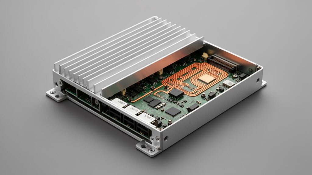
Table of Contents
01 · Fanless Thermal Design: CFD, Heat Pipes and Liquid Metal TIM
Industrial computing environments demand thermal solutions that operate reliably without mechanical cooling components. Fan-based cooling introduces multiple failure modes: bearing wear causes eventual seizure, dust accumulation reduces airflow efficiency, and acoustic noise limits deployment in operator-proximate applications. Our engineering approach centers on passive convection coolingthrough CFD-optimized chassis design.
CFD Simulation for Fanless Chassis (AL6061-T6, 237 W/m·K)
Computational Fluid Dynamics (CFD) simulation enables precise thermal modeling before physical prototyping, ensuring optimal heat dissipation across all operating conditions. The simulation analyzes natural convection patterns, fin geometry optimization, and heat spreading from concentrated CPU dies to distributed chassis surfaces.
Our platforms utilize fin-structured aluminum chassis with thermal conductivity of 237 W/(m·K), providing exceptional heat spreading from internal components to the external enclosure surface. The aluminum alloy (AL6061-T6) combines high thermal conductivity with mechanical strength for rugged deployment environments.
| Thermal Solution | TDP Support | Target Application |
|---|---|---|
| Passive Unibody Heatsink | 6–15W | Standard IoT Gateways |
| Liquid Metal TIM + Dual Heat Pipes | 15–55W | Core i5/i7 Automation Controllers |
| Hybrid Thermal (Passive Core + Active GPU) | 55–150W+ | MXM Series / 32 TOPS Edge AI Processing |
Hybrid Thermal for High-TDP GPU Modules (up to 150W+) Heat Pipe and Liquid Metal TIM
As industrial applications shift towards heavy edge inference, pure passive cooling becomes a bottleneck. For high-compute nodes utilizing RK3588 (6 TOPS on-die NPU, up to 32 TOPS with M.2 accelerator) or discrete MXM GPU modules, we deploy a Hybrid Thermal Architecture. This completely isolates the passive CPU/SOM chamber from the accelerated GPU chamber, utilizing targeted, industrial-grade active exhaust strictly for the high-TDP accelerators. This ensures the core operating system remains thermally secure even if ambient conditions spike.
0.02°C/W Thermal Resistance Extended Operating Temperature Rang
For high-TDP processor configurations (up to 45W), embedded heat pipestransfer thermal energy from the CPU die to distributed fin arrays. Heat pipes utilize phase-change thermal transfer: a working fluid (typically water or ammonia) evaporates at the heat source, travels through the pipe core, and condenses at the cooler fin array, releasing latent heat. The sintered copper powder wick structure returns the condensed liquid to the evaporator through capillary action.
High-TDP systems also utilize liquid metal thermal interface material (TIM)achieving thermal resistance as low as 0.02°C/W—significantly lower than conventional thermal paste (0.2–0.5°C/W). The gallium-based alloy composition eliminates the pump-out and dry-out degradation that affects paste TIMs over multi-year deployments, ensuring consistent thermal performance across 10+ year lifecycles.
-40°C to +80°C Operating Range (No Throttling)
Selected industrial platforms are validated for extended operating temperatures from -40°C to +80°C (standard configurations run -20°C to +60°C). This range addresses cold storage logistics(-25°C typical), outdoor kiosk installations, and high-ambient factory environments near furnaces or ovens. The thermal design maintains stable operation without throttling across this range—a critical requirement for applications where consistent cycle times determine production throughput.
02 · Industrial DC Power: 9–36V Wide Input with 4000V Isolation
Industrial DC power systems experience significant voltage fluctuations, transients, and ground potential differences that exceed the tolerance of consumer-grade power supplies. Factory power rails derived from PLCs, motor drives, and battery systems can swing from 18V (depleted 24V battery) to 36V (charging float voltage) during normal operation—a 2:1 ratio that requires wide-input DC-DC conversion.
9–36V Wide DC Input with OVP, RVP, UVLO
Our platforms accept 9-36V DC input, accommodating both 12V automotive systems and 24V industrial rails across their full operating range. The internal DC-DC converter maintains stable 5V and 3.3V logic rails regardless of input voltage variations, preventing brown-outs during motor start events from causing processor resets or memory corruption.
The wide input range also addresses installation flexibility: the same platform deploys in mobile equipment (12V nominal), warehouse AGVs (24V battery), and fixed automation cells (24VDC rail) without power supply modifications.
| Protection Feature | Specification | Failure Mode Addressed |
|---|---|---|
| Over-Voltage Protection (OVP) | Up to 60V transient | Load dump, regenerative braking spikes |
| Reverse Polarity Protection (RVP) | Non-destructive | Wiring errors during field installation |
| Under-Voltage Lockout (UVLO) | Graceful shutdown | Battery depletion, filesystem protection |
| Optical Isolation | 4000V RMS | Ground loops, common-mode noise |
4000V Optical Isolation on Power Input (Ground Loop Prevention)
The 4000V optical isolation integrated into DC-DC converter stages creates a galvanic barrier between the power input and system logic. This isolation prevents ground potential differences—which can exceed 50V in industrial installations with long cable runs—from corrupting communication channels (CAN, RS-485, Ethernet) or causing erratic system behavior.
Ground loops are particularly problematic in machine vision applications where high-current actuators and sensitive camera interfaces share the same equipment ground. The optical isolation barrier ensures that motor PWM noise does not couple into the image acquisition path, preserving inspection accuracy.
03 · EMC Compliance: Shielding, Standards and MIL-STD-810G
Factory floors contain VFDs (Variable Frequency Drives), arc welders, induction heaters, and radio systems that generate significant electromagnetic interference across the frequency spectrum from DC to GHz. Industrial PCs must operate reliably in this environment without data corruption, unexpected resets, or communication failures—requirements codified in the EN 61000-6-2 industrial immunity standard.
Unibody Faraday Cage: 2–3mm Wall, 40dB @ 1GHz
Steel and aluminum unibody enclosure construction creates a continuous Faraday cage around sensitive electronics. The 2.0–3.0mm wall thickness provides both mechanical protection and EMI shielding effectiveness exceeding 40dB at frequencies up to 1GHz. Conductive anodize surface treatment ensures electrical continuity across panel joints and access covers.
I/O connector panels use conductive gaskets and spring-finger contacts to maintain shielding integrity even with cables connected. This 360° shielding approach prevents EMI ingress through I/O apertures—a common weakness in consumer-grade enclosures.
| Standard | Test Description | Level Achieved |
|---|---|---|
| EN 61000-4-2 | Electrostatic Discharge (ESD) | ±8kV air / ±4kV contact |
| EN 61000-4-4 | Electrical Fast Transient (EFT) | Level 4 (±4kV) |
| EN 61000-4-5 | Surge Immunity | Level 3 (±2kV) |
| EN 61000-4-6 | Conducted RF Immunity | 10V/m, 150kHz–80MHz |
| EN 61000-6-2 | Industrial Immunity (Composite) | Full Compliance |
MIL-STD-810G: 15G Shock, 1 Grms Vibration (5–500Hz)
Extended temperature models also meet MIL-STD-810G Method 516.6 for mechanical shock (15G, 11ms half-sine) and Method 514.6 for vibration (5–500Hz, 1 Grms). These specifications address AGV floor travel, forklift-mounted applications, and installations near stamping presses or CNC machines where continuous vibration would cause connector fretting or solder joint fatigue in consumer-grade equipment.
Facing specific EMC or thermal challenges?
Skip the generic datasheets. Request our 3D STEP models to validate your mechanical fit, or consult directly with our architecture team to review your I/O and isolation requirements.
04 · PCB-Level Protection: Conformal Coating and Interface Isolation
Beyond standard ruggedness, industrial deployments in chemically active or high-humidity environments require specialized protection at the PCB level. IP65 enclosures protect against external water and dust, but internal condensation during temperature cycling can still cause corrosion and electrical shorts on unprotected circuit boards.
Conformal Coating (IPC-CC-830B): 25–75μm
Conformal coating applies a thin protective polymer layer (25–75μm) over the entire PCB assembly, encapsulating components and solder joints against moisture, salt spray, and chemical exposure. Our automated coating process meetsIPC-CC-830B qualification requirements for humidity resistance (500 hours @ 95% RH) and salt spray survival (IEC 60068-2-52).
Coating material selection depends on the deployment environment:
- Acrylic (AR): General-purpose, easy rework, excellent humidity resistance
- Silicone (SR): High-temperature stability, flexible for thermal cycling
- Polyurethane (UR): Chemical resistance for washdown environments
- Parylene: Ultra-thin, pinhole-free for medical/semiconductor applications
4000V Isolated RS-232/485, CAN Bus and Ethernet
Beyond power isolation, communication interfaces require protection against ground potential differences and transient energy injection. All RS-232/485, CAN Bus, and Ethernet interfaces include 4,000V galvanic isolation using optical or magnetic coupling.
This isolation serves as a “firewall” between the industrial PC and field devices, preventing faults in sensors, actuators, or cables from propagating to the computing system. In multi-machine installations, it also blocks ground loop currents that would otherwise flow through communication cables.
Signal Integrity: The 60Ω CAN Bus Rule
For mission-critical CAN Bus networks, signal reflection is a primary cause of packet loss. Our hardware-level implementation strictly accounts for the 60Ω terminal resistance rule. Instead of leaving termination to chance or external dongles, our carrier boards feature easily configurable jumper settings for standard CAN terminal resistance. When combined with our native CAN communication support across low, medium, and high speeds, this ensures flawless signal integrity across long cable runs, even in environments with extreme common-mode noise.
05 · Lifecycle Management: Locked BOM, PCN and 10-Year Availability
Industrial deployments span 7–15 years—far exceeding the 2–3 year refresh cycles of consumer IT equipment. The computing platform must remain available for spares, repairs, and fleet expansion throughout this period. Component obsolescence, undocumented substitutions, and “equivalent” replacements that cause subtle behavioral differences are existential risks for OEM equipment manufacturers.
10-Year Platform Availability with 6-Month Last-Time-Buy Notic
We commit to 10-year platform availability from product launch for AE-3588 series (aligned with Rockchip’s published production commitment) and 7+ years for modular AX series x86 platforms.
When components approach end-of-life, we provide 6-month Product Change Notification with a last-time-buy window, allowing customers to secure bridge stock for remaining deployment lifecycle.”
Fixed BOM Control: No Silent Substitutions
Our Locked BOM (Bill of Materials) approach freezes the component specification after OEM validation, preventing performance drift from undocumented substitutions. The freeze scope includes:
- CPU/SoC: Exact part number, stepping, and manufacturing source
- Memory ICs: Manufacturer, density, speed grade, and die revision
- Storage Controller: Firmware version and NAND configuration
- Power Management ICs: Switching frequencies and output tolerances
PCN Workflow: 6-Month Notice, Form-Fit-Function Assessment
When component changes become unavoidable (supplier discontinuation, safety errata), all modifications trigger a formal Product Change Notice (PCN) with impact assessment against Form-Fit-Function criteria. Customers receive advance notification with technical evaluation and optional bridge stock reservation before the change is implemented. This workflow ensures that validated production systems are never surprised by behavioral changes from “equivalent” components.
Engineering FAQ
Frequently asked questions
Common questions from senior engineers reviewing thermal, power, EMC, protection and lifecycle requirements for industrial PC deployment.
What is the typical thermal design power (TDP) supported by fanless industrial PCs?
Our fanless platforms support TDP ranging from 6W (Atom-class) to 55W (Core i5/i7 U-series with configurable PL1/PL2 turbo) through CFD-optimized heatsink designs. Higher-TDP configurations utilize embedded heat pipes and liquid metal TIM for enhanced thermal transfer, achieving thermal resistance as low as 0.02°C/W.
Extended-range Edge AI platforms with MXM GPU modules can dissipate 150W+ through hybrid thermal architecture — passive core CPU chamber isolated from actively-cooled GPU chamber.
How does 4000V isolation protect against ground loops in industrial deployments?
The 4000V optical isolation creates a galvanic barrier between power input and system logic, preventing ground potential differences from corrupting communication channels (CAN, RS-485, Ethernet) or causing erratic system behavior. In industrial installations with long cable runs, ground potential differences can exceed 50V.
The isolation barrier stops motor PWM noise, VFD switching transients, and ground loop currents from coupling into sensitive interfaces. Note: 4000V is the withstand voltage verified by 1-minute dielectric test, not a continuous working voltage.
What is the difference between conformal coating and IP65 enclosures?
IP65 enclosures protect against external dust and water jets, but internal condensation can still occur in temperature cycling environments where humid air enters through breather vents and condenses on cold surfaces.
Conformal coating (IPC-CC-830B, 25–75 µm polymer layer) provides PCB-level protection against moisture, salt spray and chemical exposure regardless of enclosure rating.
For genuine washdown or coastal deployments, both are used together: IP65/IP67 enclosure for external protection, conformal coating for long-term condensation resistance.
How long is the guaranteed product lifecycle for industrial PCs?
Availability depends on the underlying silicon roadmap, not on marketing claims:
- AE-3588 series — 10+ years, aligned with Rockchip’s published production commitment
- AX series (modular x86) — 7+ years, with CPU generation swap possible without changing the carrier board or enclosure
- AE-NJ60BT (Jetson Orin NX) — tracks NVIDIA’s published Jetson product lifecycle
All platforms sit on Fixed BOM Control with 6-month PCN notice and a last-time-buy window before any change takes effect.
What EMC and immunity standards do BITECH industrial PCs comply with?
All platforms comply with EN 61000-6-2 (Industrial Immunity Composite) including:
- EN 61000-4-2 ESD — contact ±4kV, air ±8kV
- EN 61000-4-4 EFT — Level 4 (±4kV)
- EN 61000-4-5 Surge Immunity — Level 3 (±2kV)
- EN 61000-4-6 Conducted RF Immunity — 10 V/m, 150kHz–80MHz
Products also carry CE, UKCA, FCC and RoHS certifications. Extended-temperature and mobile platforms are additionally tested to MIL-STD-810G methods for shock (15G, 11ms) and vibration (5–500 Hz, 1 Grms).
What operating temperature range is available for fanless industrial PCs?
Standard configurations operate from -20°C to +60°C without fans. Extended-temperature configurations support -40°C to +80°C for cold storage logistics, outdoor kiosk installations, unheated roadside enclosures and high-ambient factory environments near furnaces or ovens.
Extended-temperature units are chamber-verified per unit before shipment (cold-soak boot at -40°C, sustained full-load at +80°C) as part of the per-unit QC process. Neither range causes thermal throttling on validated platforms.
What is the 60Ω CAN bus termination rule and why does it matter?
A properly terminated CAN bus has two 120Ω terminating resistors, one at each end of the bus. Measured across the bus with the network powered off, they appear in parallel and read approximately 60Ω.
- If a multimeter reads 120Ω — one terminator is missing (or the bus is broken between the meter and one terminator)
- If it reads 40Ω — there is one extra 120Ω terminator somewhere on the bus
BITECH platforms provide jumper-configurable termination on the carrier board, so integrators don’t need external termination dongles. This ensures signal integrity across long cable runs and high-EMI environments.
Next Step
Ready to spec a platform against these principles?
Send us the constraints that matter for your deployment — thermal envelope, isolation requirements, EMC target, lifecycle horizon — and we’ll come back with a platform recommendation and, if needed, a custom carrier or full ODM proposal.
Standard platforms, custom carrier, or full ODM. Response within 2 business days from a hardware engineer, not a sales script.
Start an RFQ →WhatsApp or email us if the question is easier to answer in a message than a form.
Prefer to keep reading? Return to the Engineering hub →
Explore Further
Products and platforms built with these engineering principles
The five principles above are not theoretical — every BITECH platform is engineered against them. Explore the platforms and solutions where each principle is most visible.
Vehicle-Mounted Industrial PC
Wide-voltage 9–36V DC input, ignition control, ISO 7637-2 transient protection, and 4000V isolated CAN — the power and thermal engineering above, deployed on trucks and mobile equipment.
Explore vehicle platform → ProductAX-234BT Edge Computer
13th Gen i5-1345U fanless, dual 2.5GbE with AMT, discrete TPM 2.0, CAN Bus, 9–36V input. Full EN 61000-6-2 immunity profile, tested to MIL-STD-810G methods.
View AX-234BT → EngineeringConformal Coating (IPC-CC-830B)
Deep-dive into acrylic, silicone, polyurethane and Parylene coatings for humidity, salt spray and chemical resistance. When PCB-level protection matters more than IP rating.
Read the guide → EngineeringGalvanic Isolation Deep-Dive
How 4000V isolation actually works on CAN, RS-485 and DIO. Withstand vs continuous working voltage, optical vs magnetic coupling, and when isolation is worth the propagation-delay cost.
Read the guide → EngineeringThe 60Ω CAN Bus Check
30-second physical-layer test with a multimeter: 60Ω healthy, 120Ω one terminator missing, 40Ω one too many. The rule from section 04 in practice.
Read the check → EngineeringLifecycle Management & PCN
10-year platform availability by product family, Fixed BOM Control, 6-month PCN with last-time-buy windows, and how architecture determines what has to change when silicon reaches EOL.
Read the policy →