
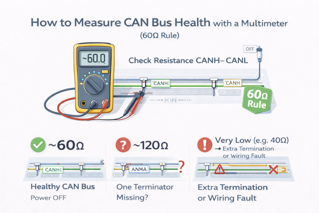
The 60Ω rule: a 30-second CAN bus check before you touch the logs

Most ‘CAN bugs’ aren’t software. They’re the physical layer — and a 10 multimeter finds them faster than any analyzer. Here’s the check every installer and engineer should know.

How to Measure CAN Bus Health with a Multimeter (60Ω Rule)-Bitech

Two 120Ω terminators in parallel across CANH/CANL read ~60Ω on a powered-off bus — the fastest health check in the field.

BITECH Engineering Notes · ~4 min read

You’ve got intermittent CAN errors. Frames dropping, a node that works on the bench and fails in the field. The instinct is to open the logs or reach for a protocol analyzer.

Do this first. It takes 30 seconds and costs nothing.

Why 60Ω

A high-speed CAN bus is a twisted pair with a 120Ω terminator at each physical end — they absorb the signal so it doesn’t reflect back and corrupt frames. Two terminators, one at each end, no more, no less.

Those two 120Ω resistors sit in parallel across CANH/CANL. Two 120Ω in parallel = 60Ω. So measuring resistance across the bus tells you whether both terminators are actually there.

The check

  1. Power off the system. Not optional — active transceivers skew the reading. On a vehicle, let the network sleep or disconnect the battery negative.
  2. Set the multimeter to resistance (Ω).
  3. Measure between CANH and CANL (on a vehicle: OBD-II pin 6 and pin 14).
  4. Read against the table below.
ReadingWhat it means
~60ΩHealthy — both terminators present
~120ΩOnly one terminator — the second is missing or open
~40ΩA third terminator is installed — remove the extra
~0ΩShort between CANH and CANL, or a wiring fault
very high / fluctuatingNo termination, or an open in the harness

A few ohms off 60 is normal — cable, connectors, and transceiver impedance all nudge it. You want “close to 60,” not a lab number.

What it does NOT tell you

This is where people get a false sense of safety. A resistance check confirms the total termination — nothing more:

  • It can’t confirm placement. ~60Ω could be two correct end terminators, or a single 60Ω resistor in the middle, or terminators on the wrong nodes. Only physical inspection confirms they’re at the true ends.
  • It can’t see software-switched terminators. Some devices enable termination after power-up — invisible to a cold resistance test. Check the manual.
  • It won’t reveal shorts to ground or supply — those need separate CANH/CANL-to-ground and -to-power measurements (should read megohms).
  • It won’t show the waveform. Bit timing and reflections still need a scope or CAN analyzer. The 60Ω check just tells you whether it’s worth reaching for one.

Why it’s worth the 30 seconds

A missing terminator is the classic trap: a bus with only one terminator often works temporarily, then turns unreliable and fails — usually after it’s already in the field. Catching it at 60Ω on install is a lot cheaper than catching it at 2 a.m. on a customer’s line.

And the rule travels: EV/BMS packs, AGVs and AMRs, robots, industrial controllers — anywhere CAN runs, 60Ω is the same first clue.

The takeaway

Before the oscilloscope, before the analyzer, before the logs: power off, measure CANH–CANL, check it’s near 60Ω. If it isn’t, you’ve found your problem before wasting an hour on software that was never broken.

At BITECH we build industrial and edge-AI computers with native, hardware-level CAN / CAN FD controllers — not USB-CAN bridges — and 4000V-isolated CAN where the deployment needs it, so the physical layer is sound before termination even enters the picture.

Related products & solutions

Native CAN / CAN FD controllers and isolation options across BITECH platforms.
Interface Isolation Guide
Where 2.5KV, 3KV and 4KV isolation belong on CAN, RS-485 and digital I/O.
CAN as the motion-control backbone alongside Ethernet vision and safety I/O.
Need native, isolated CAN?

Tell us the node count, bitrate and isolation you need.

Our engineers will match your deployment to a BITECH box PC with hardware-level CAN / CAN FD and the right transient protection.

Talk to an Engineer
CAN Bus 60Ω Rule — FAQ | BITECH

CAN Bus 60Ω Rule — Frequently Asked Questions

Preview of the FAQ block. Copy the section below into your page.

What should a healthy CAN bus measure with a multimeter?

About 60Ω between CANH and CANL, with the system powered off. A high-speed CAN bus has two 120Ω termination resistors, one at each physical end, and they sit in parallel — two 120Ω in parallel equal 60Ω. A reading within a few ohms of 60Ω is normal, since cable resistance, connector contact resistance and transceiver input impedance all shift it slightly.

Why does a CAN bus read 60Ω and not 120Ω?

Because the two 120Ω terminators are wired in parallel across the same CANH/CANL pair, and two equal resistors in parallel give half the value — 60Ω. If you measure ~120Ω, only one terminator is present; the second is missing or open.

What does it mean if my CAN bus reads 120Ω, 40Ω, or 0Ω?
Reading (CANH–CANL, power off)What it means
~60ΩHealthy — both 120Ω terminators present
~120ΩOnly one terminator — the second is missing or open
~40ΩA third terminator is installed — remove the extra one
Near 0ΩShort between CANH and CANL, or a wiring fault
Very high / openNo termination, or an open in the harness

Only a reading close to 60Ω indicates both terminators are correctly present.

Do I have to power off the bus to measure termination?

Yes. Active CAN transceivers conduct current across the bus and skew the resistance reading, so the bus must be de-energised. On a vehicle, wait for the network to enter sleep mode after ignition off, or disconnect the battery negative terminal for an immediate result.

Does a 60Ω reading guarantee the CAN bus is wired correctly?

No. A resistance test only confirms the total termination resistance, not where the resistors are. A ~60Ω reading could be two correct end terminators, or a single 60Ω resistor placed wrongly in the middle, or terminators on intermediate nodes. It also can’t detect software-switched terminators or shorts to ground. Confirm placement by physical inspection, and use an oscilloscope or CAN analyzer for signal quality.

Can a multimeter replace an oscilloscope for CAN troubleshooting?

No — but it comes first. A multimeter checks termination and gross wiring faults in seconds and rules the physical layer in or out. It can’t show the waveform, bit timing, or reflections, which require an oscilloscope or CAN analyzer. The 60Ω rule tells you whether those tools are even needed.

Where do I measure on a vehicle?

At the OBD-II connector: pin 6 is CANH and pin 14 is CANL. You can also measure at any accessible connector or splice on the bus. Make sure the network is asleep or the battery negative is disconnected before taking the reading.

Scroll to Top
POPUP Form

Contact Us